EasyManua.ls Logo

Philips MCD908 Service Manual

Philips MCD908
33 pages
To Next Page IconTo Next Page
Page #1 background imageLoading...
Page #1 background image
Version 1.0
MCD908
© 3141 785 31300
DVD Micro theatre
all versions
Published by LX 0650 Service Audio Subject to modification
©
Copyright 2006 Philips Consumer Electronics B.V. Eindhoven, The Netherlands
All rights reserved. No part of this publication may be reproduced, stored in a retrieval
system or transmitted, in any form or by any means, electronic, mechanical, photocopying,
or otherwise without the prior permission of Philips.
Handling chip components ...........................................................1-1
Leadfree and safety information ....................................................1-2
Technical specification ...................................................................2-1
Service tools .................................................................................2-1
Service measurement setup ..........................................................2-2
Connections and controls ......................................................3-1...3-5
Software version check and upgrading .........................................4-1
Block diagram ................................................................................5-1
Wiring diagram .............................................................................6-1
VFD Board
circuit diagram ..........................................................................7-1
layout diagram ..........................................................................7-2
Tuner Board
circuit diagram ..........................................................................8-1
layout diagram ..........................................................................8-2
AMP Board
circuit diagram ..................................................................9-1...9-2
layout diagram .........................................................................9-3
CPU Board
circuit diagram. .......................................................................10-1
layout diagram ..............................................................10-2...10-3
Power Board
circuit diagram. .......................................................................11-1
layout diagram ........................................................................ 11-2
DVD MPEG Board
circuit diagram. .............................................................12-1...12-3
layout diagram ........................................................................12-4
Exploded view diagram ...............................................................13-1
Mechanical partslist .....................................................................13-2
Electrical partslist...............................................................14-1...14-2
TABLE OF CONTENTS

Other manuals for Philips MCD908

Question and Answer IconNeed help?

Do you have a question about the Philips MCD908 and is the answer not in the manual?

Philips MCD908 Specifications

Picture/Display IconPicture/Display
D/A converter12bit, 108MHz
Picture enhancementHigh Def (720p, 1080i)
Video upsamplingYes
Sound IconSound
Output Power2x75W RMS / 2500W PMPO
Sound EnhancementVacuum Tube Preamplifier, Class 'D' Digital Amplifier
Sound SystemDolby Digital
Power IconPower
Power supply110-240V
Frequency50/60 Hz
Weight incl. Packaging23 kg
Dimensions IconDimensions
Set dimensions (W x H x D)250 x 180 x 280 mm
Main speaker dimensions (W x H x D)205 x 329 x 240 mm
Packaging dimensions (W x H x D)755 x 417 x 330 mm

Summary

Handling Chip Components

General Handling Procedures

Basic guidelines for handling chip components to prevent damage.

Dismounting and Mounting Techniques

Methods for removing and installing chip components.

ESD and Safety Precautions

Detailed information on ESD risks and essential safety measures.

Laser Product Safety Warning

Warning regarding invisible laser radiation when the unit is open.

Lead-Free Soldering Information

Identification and Procedures

Guidance on identifying lead-free sets and proper soldering techniques.

Service Instructions and Safety

Post-Repair Safety Checks

Essential safety inspections after completing a repair.

Technical Specifications

System, Speaker, and Subwoofer Specs

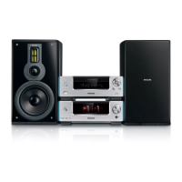
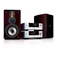
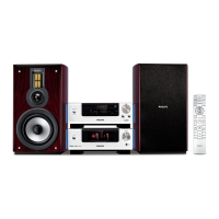
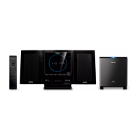
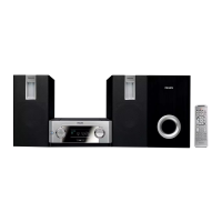
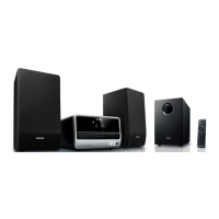
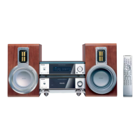
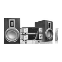
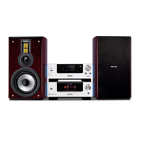
Technical details for system, speakers, and subwoofer.

DVD, Amplifier, Tuner, and Remote Specs

Technical data for DVD, amp, tuner, and remote functions.

Service Tools

Required Service Tools List

A list of specialized tools necessary for repairs.

ESD Protection Equipment

Available ESD Protection Gear

List of equipment to prevent electrostatic discharge damage.

Service Measurement Procedures

Tuner Measurement Setup

Setup for measuring FM/AM tuner performance.

CD and Recorder Measurement Setup

Measurement procedures for CD and recorder functions.

Connection and Controls Overview

Remote Control Functionality

Detailed explanation of remote control buttons and their functions.

Front Panel Controls and Display

Overview of the main unit's buttons and display interface.

System Connections and Setup

Speaker Placement Guidelines

Instructions for optimal speaker positioning.

Remote Control Operation Details

Further specifics on remote control operations.

Physical Connections Guide

Connecting Speakers and Control Cable

Steps for connecting speakers and the control cable.

Connecting to Television Video Inputs

Instructions for TV video connections (Composite, Component, S-Video).

External Device Connections

RF Modulator and Antenna Setup

Connecting via RF modulator and setting up FM/MW antennas.

Power Cord and Additional Equipment

Connecting power and other external devices.

Troubleshooting Common Issues

Power, Picture, and Audio Problems

Solutions for power, picture, and sound related issues.

Playback and System Response Issues

Troubleshooting playback errors and system unresponsiveness.

Feature Activation and Radio Reception

Resolving issues with features and radio broadcast noise.

Software Version and Upgrading

Checking MPEG and CPU Software Versions

Procedures to check software versions of MPEG and CPU.

MPEG Software Upgrading Process

Steps for downloading and installing firmware updates.

Set Block Diagram

System Block Diagram Overview

Visual representation of the system's functional blocks.

Set Wiring Diagram

System Wiring Diagram Illustration

Diagram showing electrical connections between components.

Circuit Diagram - VFD Board

VFD Board Schematic

Detailed circuit diagram for the VFD board.

Layout Diagram - VFD Board

VFD Board Component Layout

Visual layout of components on the VFD board.

Circuit Diagram - Tuner Board

Tuner Board Schematic

Circuit diagram for the tuner section.

Layout Diagram - Tuner Board

Tuner Board Component Layout

Component placement on the tuner board.

Circuit Diagram - Amplifier Board

Amplifier Board Circuit (Part 1)

Schematic for the amplifier board, first part.

Layout Diagram - Amplifier Board

Amplifier Board Layout (Part 1)

Component layout for the amplifier board, first part.

Layout Diagram - Amplifier Board

Amplifier Board Layout (Part 2)

Component layout for the amplifier board, second part.

Circuit Diagram - CPU Board

CPU Board Schematic

Detailed circuit diagram for the CPU board.

Layout Diagram - CPU Board

CPU Board Layout (Part 1)

Component placement diagram for the CPU board, first section.

Layout Diagram - CPU Board

CPU Board Layout (Part 2)

Component placement diagram for the CPU board, second section.

Circuit Diagram - Power Board

Power Board Schematic

Detailed circuit diagram for the power supply board.

Layout Diagram - Power Board

Power Board Component Layout

Visual layout of components on the power supply board.

Circuit Diagram - DVD MPEG Board

DVD MPEG Board Circuit (Part 1)

Schematic for the DVD MPEG board, first section.

Circuit Diagram - DVD MPEG Board

DVD MPEG Board Circuit (Part 2)

Schematic for the DVD MPEG board, second section.

Circuit Diagram - DVD MPEG Board

DVD MPEG Board Circuit (Part 3)

Schematic for the DVD MPEG board, third section.

Layout Diagram - DVD MPEG Board

DVD MPEG Board Component Layout

Component placement diagram for the DVD MPEG board.

Exploded View Diagram

Amplifier Part Exploded View

Visual breakdown of the amplifier section's components.

DVD Part Exploded View

Visual breakdown of the DVD section's components.

Mechanical Parts List

DVD Part Mechanical Components

List of mechanical parts for the DVD section.

Amplifier Part Mechanical Components

List of mechanical parts for the amplifier section.

Electrical Partslist - DVD Part

DVD Part Miscellaneous Components

List of miscellaneous electrical parts for the DVD section.

DVD Part Coils and Filters

List of coils and filters for the DVD section.

DVD Part ICs and Transistors

List of ICs and transistors for the DVD section.

Electrical Partslist - Amplifier Part

Amplifier Part Miscellaneous Components

List of miscellaneous electrical parts for the amplifier section.

Amplifier Part ICs and Transistors

List of ICs and transistors for the amplifier section.

Related product manuals