Do you have a question about the Philips MCD139 and is the answer not in the manual?
Details the different PCB versions and their features across model numbers.
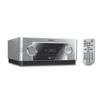
Technical specifications for the amplifier output, frequency response, and sensitivity.
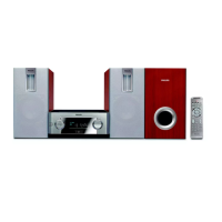
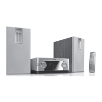
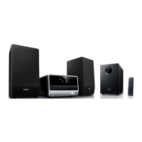
Specifications for the speaker system, impedance, drivers, and dimensions.
Specifications for the subwoofer, including impedance, driver size, and dimensions.
Technical details for the tuner, including tuning range and signal-to-noise ratio.
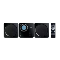
Specifications for the DVD player, such as laser type, decoding, and video output.
Specifications for the main unit, including power supply, consumption, and dimensions.
Describes the setup for measuring FM tuner performance using specific equipment.
Details the measurement setup for CD playback, including test discs and equipment.
Describes the measurement setup for recorder performance, including test cassettes and equipment.
Lists specialized tools required for servicing the unit.
Lists specific CDs required for testing and diagnostics.
Safety warning regarding electrostatic discharge and handling ICs.
Guidance on identifying and handling lead-free soldered components.
General safety instructions and checks required after repair.
Diagnostic flowchart for issues related to CD playback.
Step-by-step guide for standard CD playability repairs.
How to check CD disc playability with specific test discs.
Procedure for cleaning the CD player lens using special fluid.
Method for cleaning the CD lens using a dry brush.
Information to provide to customers after a checked unit is found fault-free.
Measuring the eye-pattern signal for jitter on the CD drive.
Measuring laser current to diagnose CD drive issues.
Measuring CD drive photodiode offsets for playability diagnosis.
Guidance on optimal placement of speakers and subwoofer for surround sound.
How to connect speakers and subwoofer to the main unit.
Options for connecting the system to a TV for video and audio.
How to connect external audio/video sources like VCRs or set-top boxes.
Instructions for connecting the FM antenna for radio reception.
Guidance on connecting the AC power cord safely.
How to connect digital audio devices using coaxial output.
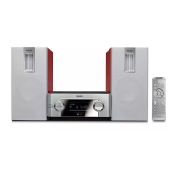
Identifies and describes the buttons and controls on the main unit.
Explains the functions of each button on the remote control.
Steps to diagnose and fix issues related to the unit not powering on.
Solutions for no picture, distorted, or black/white video output.
Troubleshooting steps for audio issues, including lack of sound or distortion.
Resolving issues with disc playback, unresponsiveness, and feature access.
Solutions for poor radio reception and non-functional remote control.
Troubleshooting for timer, clock settings, hum/buzz sounds, and bass response.
Troubleshooting steps for issues with selecting progressive scan video.
A flowchart for diagnosing faults within the main unit.
Step-by-step instructions for removing the main board.
Instructions for disassembling the control board.
Procedure for removing the power and amplifier board.
Steps to disassemble the DVD loader mechanism.
Illustration of the unit in service position A for access.
Illustration showing the unit in service position B for repair access.
Block diagram of the DVD main board components and connections.
Block diagram of the switched-mode power board.
Block diagram of the power amplifier board.
Wiring diagram showing connections between DVD pickup and main boards.
Pin assignment details for the Front Display Unit (FTD).
Voltage readings for ICs on the Key & VFD board for diagnostics.
Schematic of the Key & VFD board showing component interconnections.
Component placement diagrams for the top and bottom of the Key & VFD board.
Comprehensive list of parts for the Key & VFD board.
Schematic diagrams illustrating the Main Board's circuitry.
Component placement diagrams for the top and bottom views of the Main Board.
Circuit diagram and PCB layouts specific to certain model versions.
List of all electrical components used on the Main Board.
Table of voltage readings for ICs on the Amplifier Board.
Schematic showing the Amplifier Board's electrical layout.
Component placement diagrams for the top and bottom views of the Amplifier Board.
List of all electrical components for the Amplifier Board.
Table of voltage readings for ICs on the Power Board.
Schematic diagram of the Power Board's circuitry.
Component placement diagram for the Power Board.
List of electrical components used on the Power Board.
Table detailing adjustments for FM tuner alignment.
Schematic diagram of the Tuner Board.
Component placement diagrams for the top and bottom views of the Tuner Board.
List of electrical components for the Tuner Board.
List of mechanical and accessory parts for the main unit.
List of electrical components for the left speaker box.
List of miscellaneous electrical parts and assemblies.
| output power | 2x25W + 50W RMS / 1800W PMPO |
|---|---|
| sound enhancement | Digital Sound Control 4 modes, Dynamic Bass Boost |
| sound system | Dolby Digital |
| main speaker | 3" woofer |
|---|---|
| subwoofer type | Passive |
| playback media | DVD+RW, DVD-Video, Picture CD, Video CD/SVCD |
|---|---|
| dvd region | 1 |
| video enhancement | Progressive Scan |
| playback media | WMA-CD, MP3-CD, CD, CD-R, CD-RW |
|---|---|
| loader type | Top |
| tuner bands | FM Stereo |
|---|---|
| station presets | 20 |
| video output - analog | Component Y Pb Pr (cinch), Composite CVBS (yellow cinch), S-Video (on Hosiden) |
|---|---|
| aux in | 1x(L/R)/ RCA |
| other connections | Digital audio coaxial out, FM Antenna, Line out, DIN connection |
| set dimensions (W x H x D) | 218 x 221.5 x 90 mm |
|---|---|
| main speaker dimensions (W x H x D) | 125 x 250 x 232 mm |
| subwoofer dimensions (W x H x D) | 147 x 250 x 232 mm |