3-2 3-2
SERVICE POSITIONS
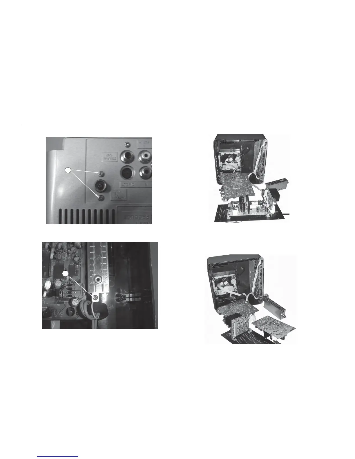
Service position A
Service position B
K
L
Dismantling of the Tuner Board
1) Loosen 2 screws "K " on the rear plate as shown in figure 11.
2) Loosen 1 screw " L " at top of the tuner pad as shown in figure 12.
Figure 11
Figure 12
Note: In some service positions the components or copper patterns of one board may risk touching its neighbouring pc
boards or metallic parts. To prevent such short-circuit use a piece of hard paper or other insulating material between them.