TUNER BOARD
TABLE OF CONTENTS
Tuner Adjustment Table .................................................................. 7-1
Circuit Diagram ............................................................................... 7-2
PCB Layout ..................................................................................... 7-3
Electrical Parts List & Voltage List ................................................. 7-4
9-1
9-1
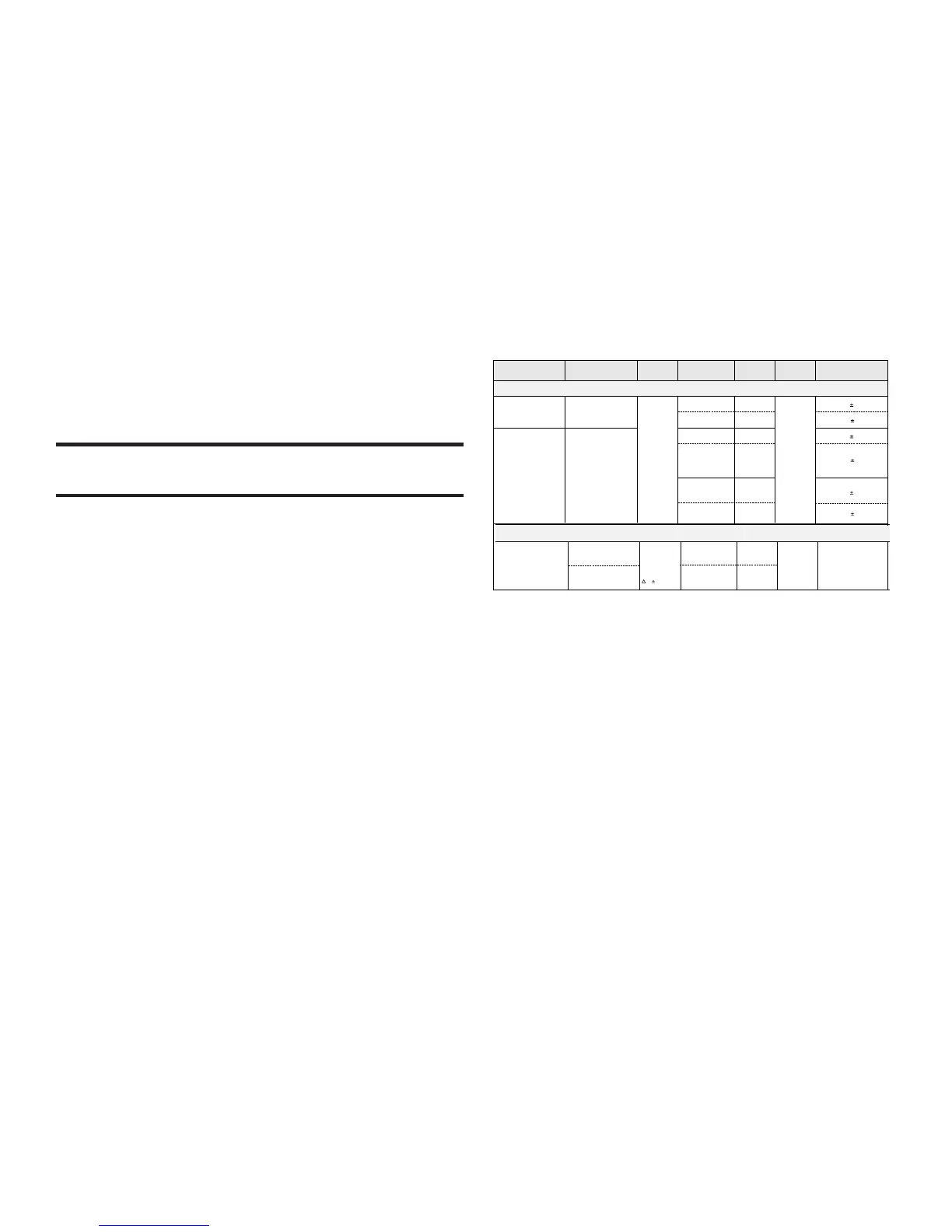
TUNER ADJUSTMENT TABLE
Waverange Input frequency Input Tuned to Adjust Output Scope/Voltmeter
VARICAP ALIGNMENT
108MHz
87.5MHz check
7.5V 1V
1.4V 0.2V
FM
87.5 - 108MHz
(50kHz grid)
1602KHz
531KHz
T005
FM
1)
If sensitivity of frequency counter is too low adjust to max. channel separation
(input signal: stereo left 90% + 9%, adjust output on right channel to minimum)
2)
RC network serves for damping the IF-filter while
adjusting the other one.
3)
For AM RF adjustments the original frame antenna has to be used!
Use Service Testprogram. By selecting the TUNER TEST test frequencies will be stored as preset frequencies automatically.
FM - RF
7.2V 1V
108MHz
87.5MHz
MAX
mod=1kHz
f=
22.5kHz
106MHz
90.1MHz
check
check
VC001
L001
MAX
1700KHz
531KHz
check
T005
1.1V
0.2V
7.2V 1V
1.1V 0.2V