Do you have a question about the Philips MCM233 and is the answer not in the manual?
| Display type | LCD |
|---|---|
| ID3 Tag display | Yes |
| RMS rated power | 20 W |
| Woofer diameter | 76 mm |
| Number of speakers | 2 |
| Supported radio bands | FM |
| Preset stations quantity | 20 |
| Power | 25 W |
| USB direct modes | Fast Backward, Fast Forward, Play/Pause, Previous/Next, Program Play, Repeat, Shuffle, Stop |
| Apple docking | No |
| Headphone connectivity | 3.5 mm |
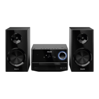
| Type | Home audio micro system |
| Product color | Black |
| Disc loading type | Front |
| Power source | AC |
| Input voltage | 110-240 V |
| Input frequency | 50 - 60 Hz |
| Playback modes | Fast backward, Fast forward, Next, Program, Repeat all, Repeat one, Shuffle |
| Disc types supported | CD, CD-R, CD-RW |
| Playback disc formats | CD audio |
| Audio formats supported | MP3, WMA |
| Volume control | Digital |
| Depth | 103.5 mm |
|---|---|
| Width | 565 mm |
| Height | 245 mm |
| Package depth | 165 mm |
| Package width | 620 mm |
| Package height | 250 mm |
| Package weight | 5500 g |
Setup for measuring FM tuner performance using RF generator and filters.
Setup for measuring AM tuner performance in a Faraday's cage.
Setup for measuring CD playback quality using signal discs.
Setup for measuring recorder performance with test cassettes.
Guidelines for handling lead-free soldering and identifying related sets.
Procedures and checks required after completing a repair.
Steps to diagnose CD playback issues using specific test tracks.
Guidance for informing customers when no fault is detected.
Method for safely cleaning the CD player lens using special solvent.
Schematic for the main board, covering initial sections.
Schematic for the main board, covering subsequent sections.
Component placement layout for the main board's component side.
PCB layout for the main board's copper (solder) side.
Schematic for the key board, detailing button and LED connections.
Component placement and routing layout for the key board.
Schematic for the LCD board, showing display driver and connections.
Component placement and routing layout for the LCD board.
Schematic for the headphone board, detailing the amplifier IC and connections.
Component placement and routing layout for the headphone board.