Do you have a question about the Philips N4307 and is the answer not in the manual?
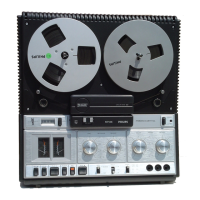
The Philips N4307 and N4308 are tape recorders, with the N4307 being a simplified version of the Stella Model ST9123A. The N4307 features a single input/output socket and omits T1, with the signal directly applied to the base of T2 through a blocking capacitor. The N4308 is electrically similar to the Stella Model ST9123A.
The Philips LFH0085 "Pocket Memo" is a miniaturized, battery-operated, cassette-loaded dictation machine. It is a completely self-contained unit, with the battery, micro-cassette, and combined microphone/loudspeaker all housed within its pocket-sized casing. A socket is provided for optional stethoscope headphones, which can be used in place of the internal loudspeaker. The LFH0085 also supports re-recording of recorded material onto Philips EL3581, EL3582, or LFH0084 dictation machines via an inter-connecting dubbing (copying) lead. It operates on a 9-volt battery (PP3 or equivalent) drawing approximately 35 mA. A battery check feature is included: by depressing the top of the side rocker switch and pressing the battery check control (located above the volume control), an audible tone from the loudspeaker indicates a good battery.
For dismantling the LFH0085, first remove the battery and tape cassette. Withdraw the plastic cap from the headphone socket, then remove screws from the back and top. Lay the machine face down, depress the record button, and lift off the rear casing. Ease the internal assembly upwards, freeing it from the front casing. Remove the safety button and foam rubber damping pad for safekeeping. Reassembly is the reverse process, ensuring battery leads are positioned in the provided slots. To remove the printed panel, set the record button and rocker switch to the rest position or the desired test position. Note or mark the position of the motor switch (S1) slider for future reference, then slacken the screw securing the actuator bracket and disengage it from the slider. Free the lead to the headphone socket.
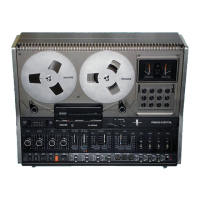
The N4307 and N4308 models are four-track, two-speed, mains-operated, tropicalized tape recorders. They utilize an electrically similar chassis, employing ten transistors and three diodes. Recording facilities include signal input mixing, loudspeaker or headphone monitoring, and a meter-type recording level indicator. These recorders can function as a microphone, radio, or pick-up amplifier. When used with the "Stereo" pre-amplifier EL3787A/00A, Stereo playback/Multiplay/Duoplay is also possible. The mains supply is 110, 127, 200-250 volts A.C. The frequency response is 60-14,000 Hz at 3¾ i.p.s. and 80-8000 Hz at 1⅞ i.p.s.
Input specifications:
Output specifications:
To remove the case of the N4307/N4308, remove the lid, pull off the four control knobs, the speed change knob, and undo the four (or five, depending on the model) ornamental screws. Take off the cover plate, disconnect the speaker leads and case screening lead (which are usually slide-on connectors but may be soldered), and lift out the chassis. The chassis can be operated outside the cabinet with normal care.
For printed panel removal on the N4307/N4308, access is gained by setting the track switch to the "PAR" position and the tape speed to 1⅞ i.p.s., then undoing the four screws securing the printed panel frame to the chassis. The frame and printed panel can be removed to the extent of the connecting leads, taking care not to bend or deform the switch blades of S4(b). When refitting the printed panel frame, ensure the switch operating levers are correctly engaged with the switch sliders and that S4(a) and S4(b) operate properly.
Recording Bias Current: The recording bias current should be 18mV (measured as a voltage), with an acceptable range of 10-25mV. To set this, switch to "Record," set the track selector switch to "1-4," and adjust R441 until an A.C. millivoltmeter reads 18mV at MP1. For track position "2-3," the same reading should be obtained at MP2 by adjusting R442. The overall frequency response should be checked, and further adjustments to the bias current may be made to achieve the desired response. Reducing bias current increases treble response, while increasing it reduces treble response. If the bias current falls below the lower limit, it can cause distortion at high modulation levels. If it exceeds the upper limit, it will result in poor treble response. If, after adjustment, the bias current remains outside the specified range, a defect in the record/playback head or amplifier circuitry should be suspected.
Modulation Level Indicator Calibration: Set the track selector switch S2 to track "1-4" (or "2-3"), turn the Radio/Phono record level control R444 to maximum, and depress only the "Record" key. Apply a 1 kHz signal to pin 3, Skt1, adjusting the level to produce 3 mV (measured with an A.C. millivoltmeter) at MP1 (or MP2). The pointer of the level indicator can then be adjusted with R446 to register on the division between the red and black sectors of the scale. Remove the input signal and switch to "Record"; the meter pointer should deflect up to a maximum of 1 mm due to bias current.
Correction Coil L2 (adjusted only on replacement): Depress only the "Record" key and apply a 1 kHz signal to pin 3, Skt1, such that an A.C. millivoltmeter reads 0.775 mV at MP1, with the track selector switch S2 set to "1-4". Change the input signal frequency to 14 kHz. The voltage at MP1 should now read 3.5 mV; adjust correction coil L2 for this reading, then seal it with locking paint.
Cleaning: For optimal performance, the magnetic heads, tape guides, and capstan should be cleaned regularly. Remove the cover for access, then clean these parts with a soft cloth wrapped around a wooden stick and moistened with methylated spirits or industrial alcohol. Avoid contact between metal objects and the magnetic head faces. After approximately 500 hours of service, it is advisable to clean the following parts with methylated spirits or industrial alcohol: magnetic head faces, tape guides, capstan and pressure roller, drive belts, grooves in flywheel and pulleys, all friction-driven surfaces, brake shoes, and braking surfaces of turntables. Clean the inside of both turntables with a soft dry brush, and if necessary, clean or replace the pressure felt.