Do you have a question about the Philips NTRX500 and is the answer not in the manual?
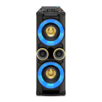
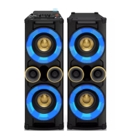
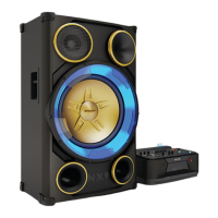
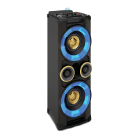
Details product variations and board usage across different versions.
Regulations for safe repair, handling, and electrical resistance checks.
Specifies operating conditions regarding temperature and humidity.
Details voltage and frequency requirements for the power supply.
Lists power consumption figures for different operating modes.
Provides electrical parameters for functions like DSC, MAX, and AUX.
Details input sensitivity and line output voltage for various connectors.
Explains DSC modes, DBB levels, and reference levels for audio processing.
Details technical specifications for USB connectivity and performance.
Specifications for the clock and timer functions, including wake-up modes.
Details USB measurement specifications at set level and performance.
Presents electrical data for tuner performance, selectivity, and sensitivity.
Specifies the type of aerial used for FM and AM reception.
Describes Bluetooth version, profiles, and indicator status.
Details electrical parameters for Bluetooth module and set level performance.
Lists active components used in the CD/MP3 playback system.
Details audio measurement parameters for CD playback.
Specifies playability criteria and test discs for CD/MP3 playback.
Details safety, EMC, tuner, and AC supply approvals for different versions.
Provides general safety regulations for unit repair and handling.
Details laser safety precautions and specifications for qualified personnel.
Instructions for removing outer parts like top, front, and bottom plates.
Steps for disassembling the CD part and various PCB boards.
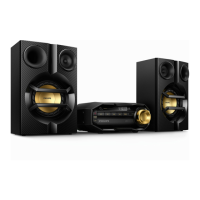
| Type | Home audio mini system |
|---|---|
| Cassette deck | No |
| Product color | Black, Blue, Gold |
| Disc loading type | Slot |
| Optical disc player | Yes |
| Number of optical discs | 1 discs |
| Recording on | USB |
| Playback modes | Program, Repeat, Repeat all, Shuffle |
| Disc types supported | CD, CD-R, CD-RW |
| Audio formats supported | MP3 |
| RMS rated power | 650 W |
| Woofer diameter | 203 mm |
| Tweeter diameter | 50 mm |
| Number of speakers | 1 |
| Peak Music Power Output (PMPO) | 8800 W |
| Equalizer bands quantity | 5 |
| USB direct modes | Fast Forward, Fast Backward, Play/Pause, Previous/Next, Repeat, Shuffle, Stop |
| USB recording modes | nstant record, programmed tracks, schedule radio program, single disc, single track |
| Apple docking compatibility | Not supported |
| Sound enhancement technology | NX Bass, Dynamic Bass Boost 3 steps, digital sound control 4 modes |
| Headphone connectivity | 3.5 mm |
| USB 2.0 ports quantity | USB 2.0 ports have a data transmission speed of 480 Mbps, and are backwards compatible with USB 1.1 ports. You can connect all kinds of peripheral devices to them. |
| Microphone connectivity | 6.3 mm |
| Accessories included | Flat pin adaptor |
| Supported radio bands | AM, FM, MW |
| Auto DJ | Metal, Party |
| USB host | Dual |
| Aux ports | 4 x RCA, DVD, Game, PC in, TV |
| DJ effects | Reverb, Beat Box, Yeah, Scratch |
| DJ mix (source A) | Audio in, Bluetooth, Disc, Tuner, USB |
| DJ mix (source B) | Audio in, USB |
| Light effect/finish | Peace, Passion, Power, Samba, Fiesta, Cielo, Custom |
| Battery type | AAA |
| Power source | AC |
| Input voltage | 100-240 V |
| Input frequency | 50 - 60 Hz |
| Number of batteries supported | 2 |
| Depth | 396.5 mm |
|---|---|
| Width | 390 mm |
| Height | 1135 mm |
| Package depth | 486 mm |
| Package width | 566 mm |
| Package height | 1252 mm |
| Package weight | 30700 g |