137
Control
R17
is
the FOCUS
control
on the
instrument
front
panel; R19
is
a trimming
potentiometer
located
internally
that is only
adjusted
initially.
The
output
signal from
the
focus
amplifier
is present
at the
emitter
of
V2026.
The h.f.
component
in
this signal
is
applied via
C2083 and
C2084
to G3
and G5
respectively.
In
addition,
this output
signal
is equally
divided
between R2073
and R2134
in
order
to control
the
focusing
electrodes
G3
and G5.
The
voltage
on G3 is
controlled
by the circuit
comprising
V2040 and
V2039.
Two
transistors
operating
in series
are used
here
to counteract
the high
voltage. The
emitter
current
applied
to
V2039 is
determined
by the
output
signal from
the focus
amplifier (via R2073)
and by the
current
from the
potentiometer
R17. The voltage
on G5 is controlled by
the circuit
comprising V2041
and V2042. Two
transistors
in series
are
also used here
because
of the high working voltage.
The
emitter
current applied to
V2041
is
determined
by the output signal from
the focus amplifier (via
R2134)
and
by the current from the triming
potentiometer R19.
CRT CATHODE
VOLTAGE REGULATION
In order
to
prevent variations
in the c.r.t. deflection sensitivities, the
—3
kV
cathode
voltage is
stabilised.
Alternating current
variations are applied via C2089 to an amplifier consisting of V2057, V2056 and V2073.
Direct current
variations are applied
to
this amplifier via
R2086
and R2087. The collector voltage
of
V2073
compensates for the voltage variations of power supply and rectifier. Consequently, the cathode voltage remains
independent of the cathode
current.
CRT CONTROLS
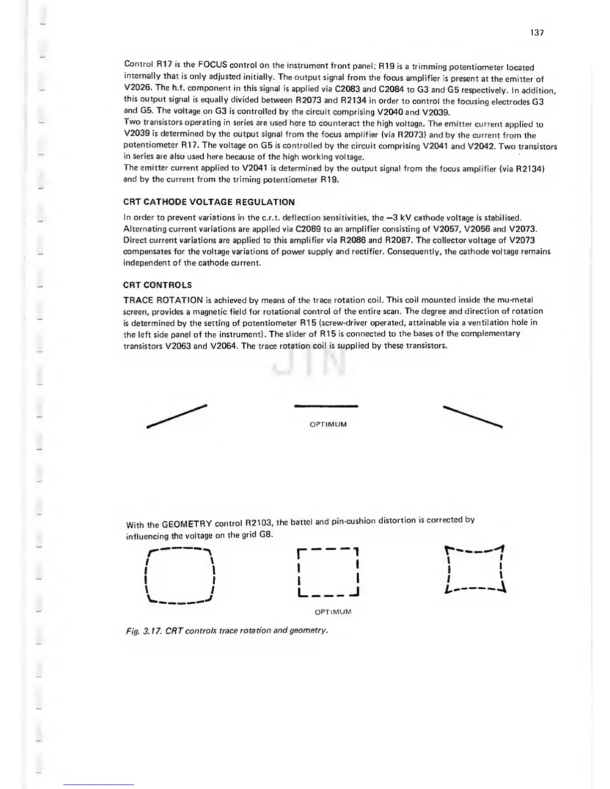
TRACE ROTATION is achieved by means of the
trace rotation coil.
This coil mounted inside the mu-metal
screen, provides
a
magnetic field
for rotational control of
the entire scan. The degree and
direction of rotation
is determined by the setting
of potentiometer R1
5
(screw-driver operated,
attainable via
a
ventilation hole in
the left
side panel
of the instrument).
The
slider of R15 is
connected to
the bases of the
complementary
transistors V2063 and V2064.
The trace
rotation coil is
supplied by these
transistors.
OPTIMUM
With
the
GEOMETRY
control
R2103,
the
battel
and
pin-cushion
distortion
is
corrected
by
influencing
the
voltage
on
the
grid G8.
OPTIMUM
Fig.
3.
17. CRT
controls
trace
rotation
and geometry.



 To Next Page