146
3.3.10.
Soldering
micro-miniature
semi-conductors
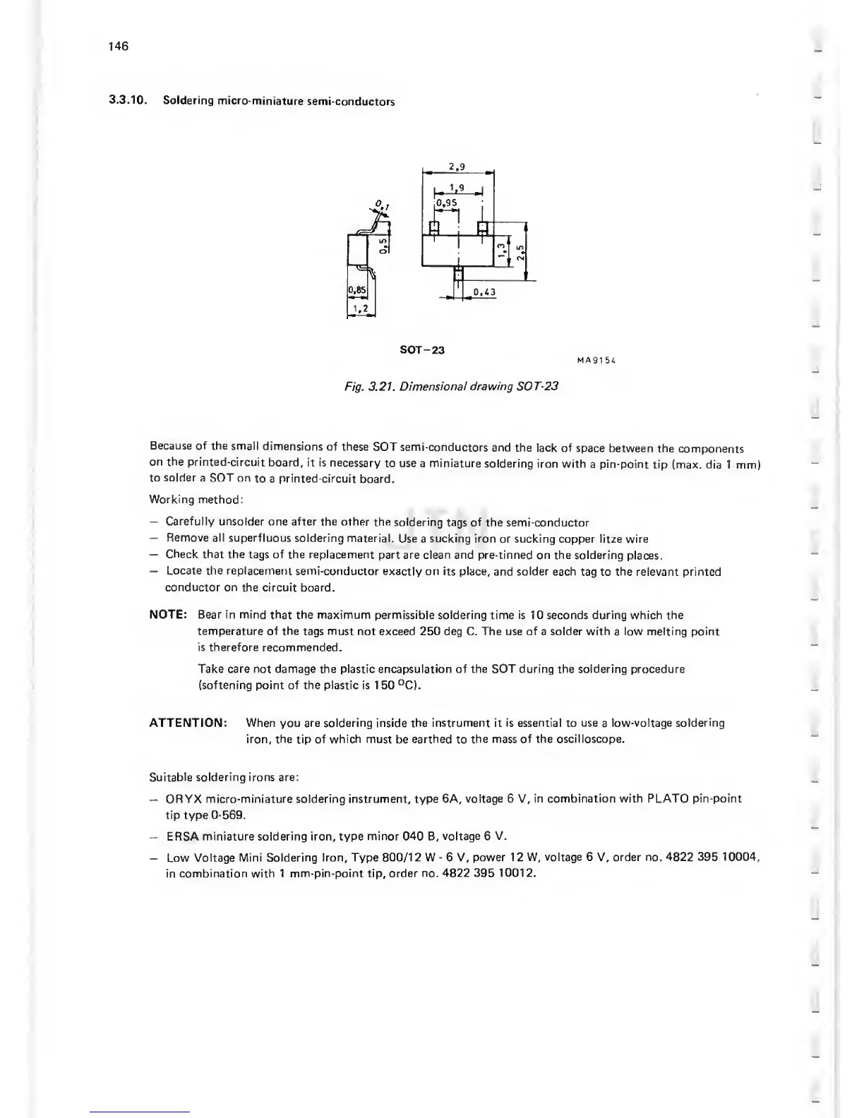
SOT
-23
MA91
54
Fig. 3.21.
Dimensional drawing SOT-23
Because of the
small
dimensions
of these
SOT semi-conductors
and
the
lack of
space
between the
components
on the
printed-circuit
board, it is
necessary
to use a miniature
soldering
iron with
a pin-point
tip (max. dia
1 mm)
to solder
a SOT on
to
a
printed-circuit
board.
Working
method;
—
Carefully unsolder one after the other
the
soldering
tags of the semi-conductor
—
Remove ail superfluous
soldering material.
Use a
sucking
iron or
sucking copper litze wire
—
Check that
the tags of the replacement
part are clean and
pre-tinned on the soldering
places.
—
Locate the replacement
semi-conductor
exactly on its place, and solder
each
tag to
the
relevant printed
conductor
on the circuit board.
NOTE: Bear in mind
that the maximum permissible soldering time
is 10 seconds during which the
temperature of the
tags
must
not exceed 250 deg C. The use of a solder with a low melting point
is therefore recommended.
Take care not damage
the
plastic encapsulation of the SOT during the soldering procedure
(softening
point of the plastic is 1
50
°C).
ATTENTION:
When you are soldering inside the
instrument
it is
essential
to
use
a
low-voltage soldering
iron, the tip of which must be earthed to
the mass of the oscilloscope.
Suitable
soldering irons are;
—
ORYX micro-miniature
soldering instrument,
type 6A,
voltage 6 V,
in combination with PLATO pin-point
tip type
0-569.
—
ERSA
miniature soldering iron,
type
minor 040 B,
voltage 6 V.
—
Low
Voltage Mini Soldering
Iron, Type 800/12 W
-
6 V,
power
12
W, voltage 6 V, order no. 4822
395
10004,
in combination with 1
mm-pin-point tip, order no.
4822
395
10012.