163
3.4.
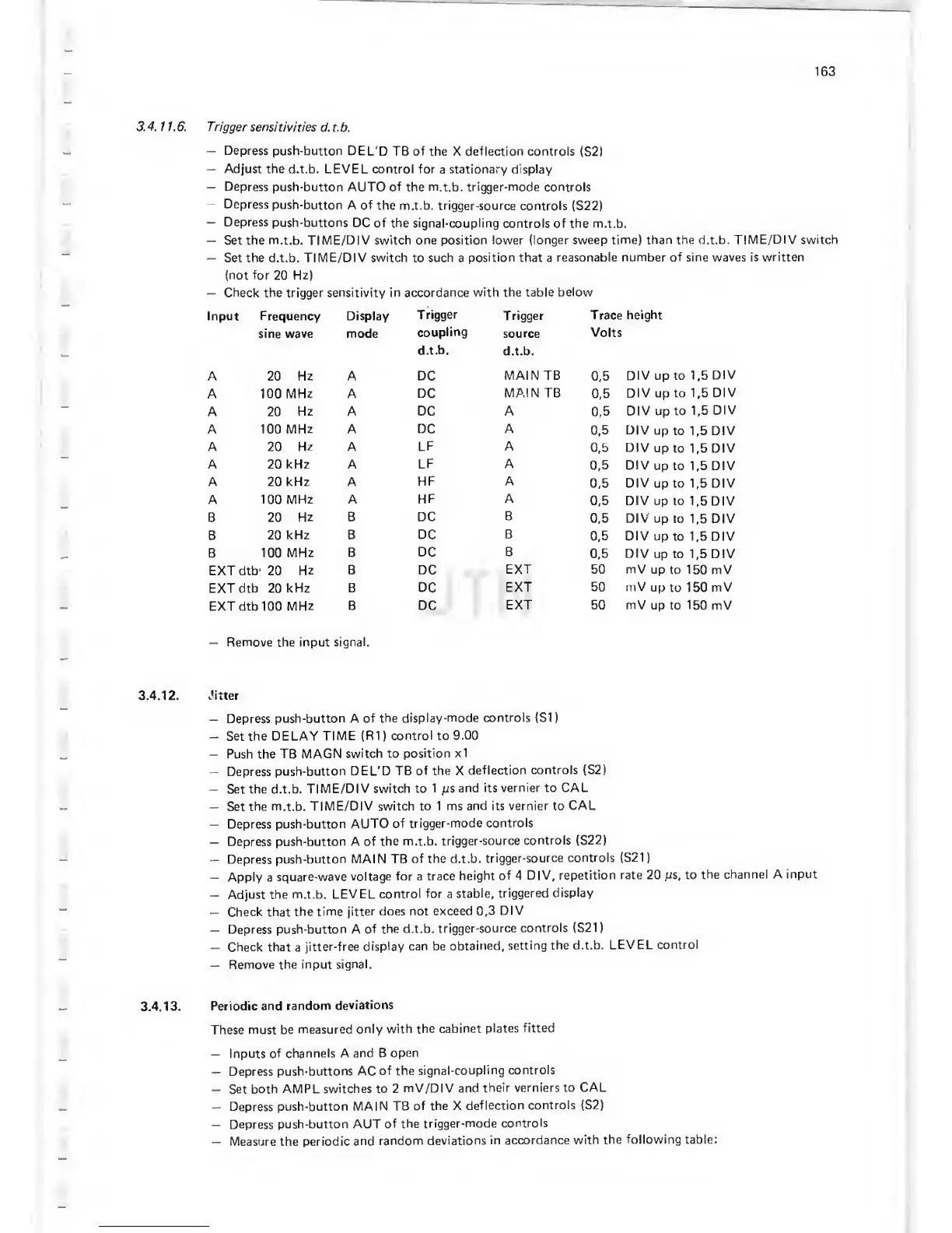
1 1.6. Trigger
sensitivities d.t.b.
—
Depress
push-button DEL'D
TB of the X deflection controls
(S2)
—
Adjust
the d.t.b. LEVEL control for
a
stationary display
—
Depress
push-button AUTO of the m.t.b. trigger-mode controls
—
Depress
push-button
A
of
the m.t.b. trigger-source
controls (S22)
—
Depress
push-buttons
DC of the signal-coupling
controls of the
m.t.b.
—
Set the m.t.b. TIME/DIV switch one position
lower (longer sweep time) than the d.t.b.
TIME/DIV switch
—
Set
the
d.t.b.
TIME/DIV switch
to
such
a
position that
a
reasonable
number
of sine
waves
is
written
(not for
20
Hz)
—
Check the
trigger
sensitivity
in
accordance
with the table
below
Input Frequency Display
Trigger
Trigger
Trace
height
sine wave mode
coupling
source
Volts
d.t.b.
d.t.b.
A 20
Hz
A
DC
MAIN TB
0,5
DIV up to
1,5
DIV
A 100 MHz A
DC
MAIN TB
0,5
DIV up to
1,5
DIV
A 20
Hz A DC
A
0,5
DIV up to 1,5
DIV
A 100
MHz A DC
A
0,5
DIV
up
to
1,5
DIV
A 20
Hz
A
LF A
0,5
DIV
up
to
1,5
DIV
A 20 kHz A
LF A
0,5
DIV
up
to
1,5
DIV
A 20 kHz A
HF A
0,5
DIV up to
1,5
DIV
A
100 MHz A
HF A
0,5
DIV
up to
1,5
DIV
B 20
Hz
B DC
B
0,5
DIV up
to
1,5
DIV
B
20 kHz B
DC
B
0,5
DIV
up
to
1,5
DIV
B
100
MHz B
DC
B
0,5
DIV
up to
1,5
DIV
EXT dtb' 20
Hz B DC
EXT 50 mV up
to 1
50
mV
EXT
dtb 20 kHz B
DC
EXT
50 mV
up
to
150
mV
EXT dtb 100
MHz
B
DC
EXT 50 mV up to 1
50 mV
—
Remove the input
signal.
3.4.12.
.litter
—
Depress
push-button A
of the
display-mode
controls (SI
)
—
Set the DELAY
TIME (R1
)
control to
9.00
—
Push the TB MAGN
switch to
position x1
—
Depress push-button
DEL'D
TB of the X
deflection
controls
(S2)
—
Set
the
d.t.b.
TIME/DIV switch to
1
;js
and
its
vernier
to
CAL
—
Set
the
m.t.b. TIME/DIV switch to 1
ms and its
vernier
to
CAL
—
Depress push-button
AUTO
of
trigger-mode
controls
—
Depress
push-button A
of the m.t.b.
trigger-source
controls
(S22)
-
Depress
push-button
MAI N TB of the d.t.b.
trigger-source
controls
(S21
)
—
Apply a
square-wave
voltage
for a trace
height of 4 DIV,
repetition
rate 20 to
the
channel A
input
-
Adjust the
m.t.b. LEVEL
control for a
stable,
triggered
display
—
Check that
the time
jitter does not
exceed
0,3
DIV
—
Depress
push-button
A
of the d.t.b.
trigger-source
controls
(S21
)
—
Check that a
jitter-free
display can be
obtained,
setting
the d.t.b.
LEVEL
control
—
Remove
the input
signal.
3.4.13.
Periodic
and random
deviations
These must be
measured
only
with the
cabinet
plates fitted
—
Inputs of
channels A and
B open
—
Depress
push-buttons AC
of the
signal-coupling
controls
—
Set
both AM
PL switches to 2
mV/DIV and
their verniers to
CAL
—
Depress push-button
MAIN TB
of the X
deflection
controls (S2)
—
Depress push-button AUT
of
the trigger-mode
controls
—
Measure the
periodic and
random
deviations
in accordance
with
the following table:
 Loading...

