175
3. 5. 1.2.
Adjustments
Matching
the
probe
to your
oscilloscope
The
measuring
probe has been
adjusted and
checked
by the manufacturer.
However,
to match
the probe
to
your
oscilloscope,
the following
manipulation
is necessary.
Connect
the
measuring pin
to
the
CAL socket
of the
oscilloscope
A
trimmer
C2
can
be adjusted through
a
hole in
the
compensation
box
to obtain
optimum
square-wave
reponse.
See
Fig.
3.35.
Fig.
3.35.
Adjusting
C2
Adjusting the h.f,
step response
The
h.f. step-response correction
network has been adjusted by the
manufacturer
to match
an
average
oscilloscope
input.
For
optimum pulse response, however, the probe can
be adjusted to
match your
particular
oscilloscope. Later readjustment
is
only
necessary
if
the probe is
to
be used with
a
different
type
of
oscilloscope, or after replacement of
an
electrical component.
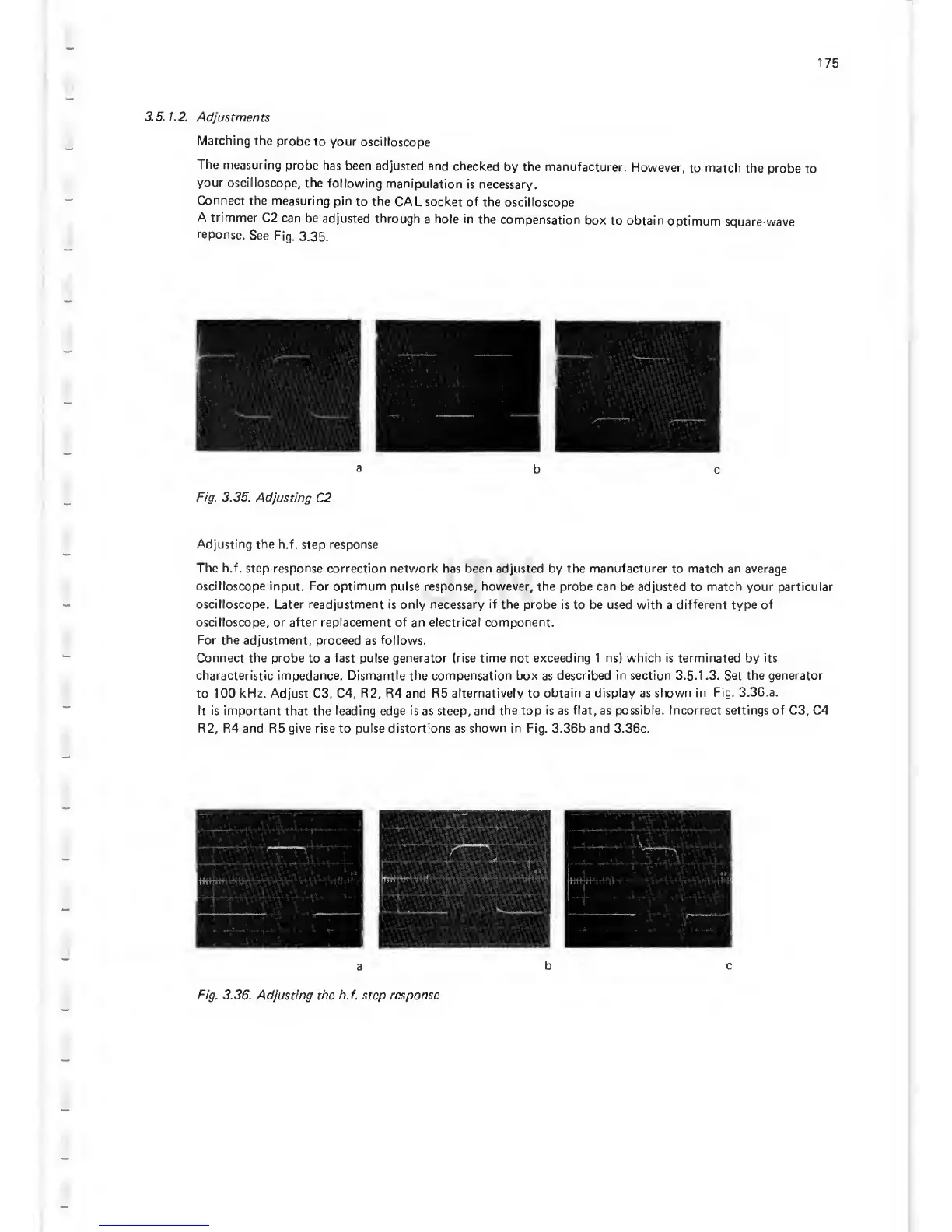
For
the adjustment, proceed
as
follows.
Connect the probe
to a
fast pulse generator (rise time not exceeding 1 ns) which is terminated
by
its
characteristic impedance. Dismantle
the
compensation box
as
described in section 3.5.1 .3. Set the generator
to 100
kHz. Adjust
C3, C4,
R2, R4
and
R5 alternatively
to
obtain
a
display as shown in
Fig.
3. 36. a.
It is important that the leading
edge
is
as
steep, and
the top is as flat, as possible.
Incorrect
settings of C3, C4
R2, R4
and
R5
give rise to pulse distortions as
shown in Fig.
3.36b and
3.36c.
Fig.
3.36. Adjusting the
h.f.
step
response
 Loading...

