176
3.5.
1.3.
Dismantling
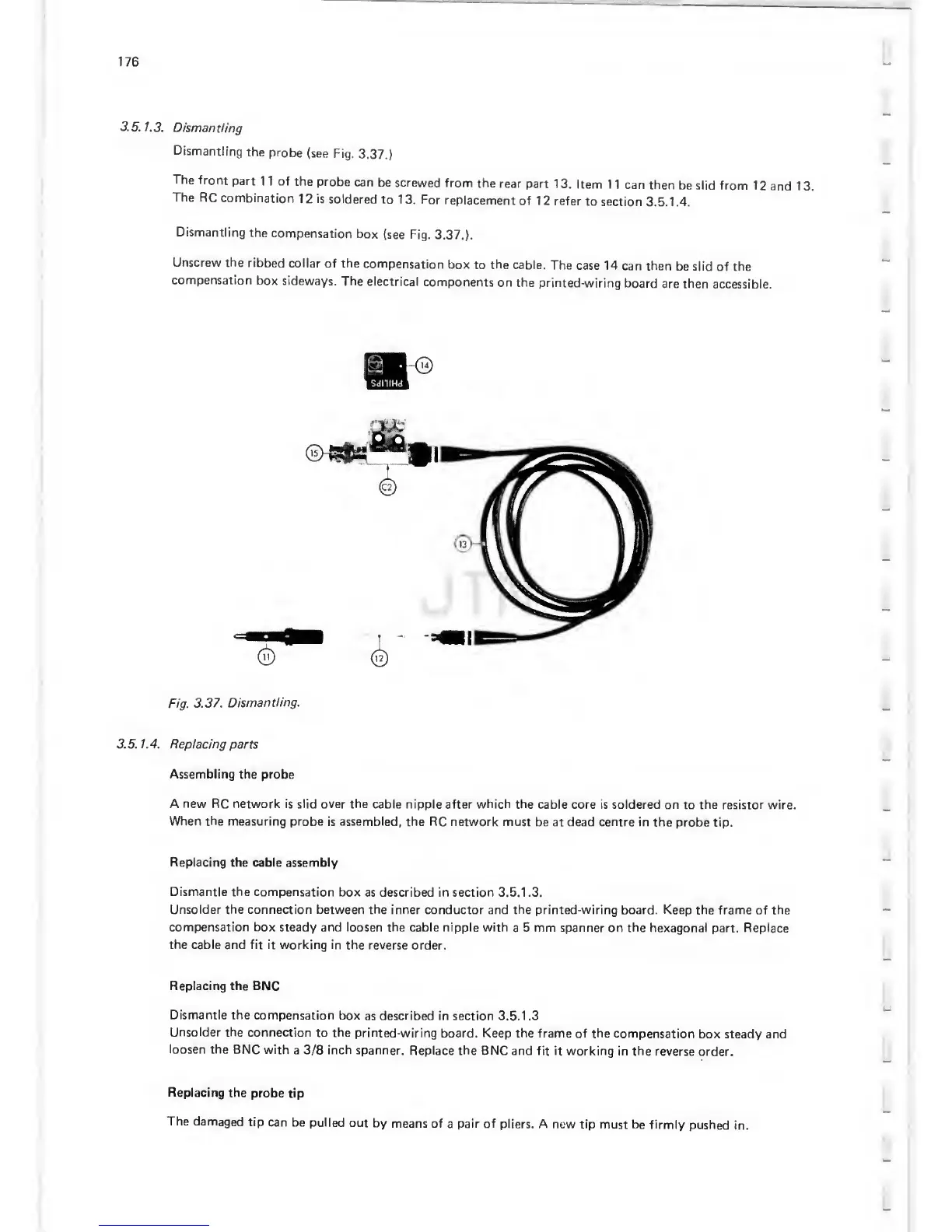
Dismantling
the
probe
(see Fig.
3.37.)
The
front
part
1 1 of the
probe
can
be screwed
from the
rear part
1
3.
Item
1
1 can then
be slid from
1
2 and
1 3.
The
RC
combination
12 is
soldered
to 13. For
replacement
of 12 refer
to
section
3. 5.1.
4.
Dismantling
the
compensation
box
(see Fig.
3.37.).
Unscrew the
ribbed
collar
of the
compensation
box
to
the
cable.
The
case 14 can
then
be slid
of
the
compensation
box sideways.
The
electrical
components
on the
printed-wiring
board
are then
accessible.
Fig.
3.37.
Dismantling.
3.5. 1.4. Replacing
parts
Assembling the probe
A
new
RC network is slid over the
cable nipple after which the cable
core is soldered on
to
the
resistor wire.
When
the
measuring probe is assembled,
the RC network must
be at dead centre in
the probe
tip.
Replacing
the cable assembly
Dismantle the compensation
box
as described in section 3.5.1 .3.
Unsolder the connection between the
inner conductor and
the
printed-wiring board. Keep
the
frame of
the
compensation box
steady and loosen the cable nipple with
a
5
mm spanner on the
hexagonal part. Replace
the cable and fit it working in
the reverse
order.
Replacing the
BNC
Dismantle the compensation
box
as
described
in section 3.5.1 .3
Unsolder
the connection
to the
printed-wiring
board. Keep the frame of the
compensation
box steady and
loosen
the BNC
with
a
3/8
inch spanner.
Replace the
BNC and fit
it
working
in the
reverse order.
Replacing
the
probe
tip
The
damaged
tip can
be pulled
out
by means
of
a
pair of
pliers. A
new tip
must be firmly
pushed in.
 Loading...

