EasyManua.ls Logo

Philips SW3600/17S User Manual

Philips SW3600/17S
14 pages
To Next Page IconTo Next Page
Page #1 background imageLoading...
Page #1 background image
Service Manual
Service
Service
Service
Service
Service
SW3600/17S
©
Copyright 2002 Philips Consumer Electronics B.V. Eindhoven, The Netherlands
All rights reserved. No part of this publication may be reproduced, stored in a retrieval system or
transmitted, in any form or by any means, electronic, mechanical, photocopying, or otherwise
without the prior permission of Philips.
Published by KC-ET0227 Service Audio Printed in The Netherlands Subject to modification
Active Subwoofer
Version 1.0
TABLE OF CONTENTS
Page
Location of PC Boards/Specifications ........................1-2
Specifications..............................................................1-2
Measurement Setup ...................................................1-3
ESD & Safety Instruction ............................................1-4
Disassembly Instructions & Service Positions ..............2
Set Block & Wiring Diagram .......................................... 3
Amplifier, I/P & LED/VR Boards .................................... 4
Mechanical Exploded View & Parts List........................5
GB
3139 785 30069
Question and Answer IconNeed help?

Do you have a question about the Philips SW3600/17S and is the answer not in the manual?

Philips SW3600/17S Specifications

General IconGeneral
BrandPhilips
ModelSW3600/17S
CategorySubwoofer
LanguageEnglish

Summary

Location of PC Boards

Specifications

Measurement Setup

ESD & Safety Instruction

ESD Handling Precautions

Precautions for handling semi-conductors susceptible to electrostatic discharge (ESD) during repair.

Safety Regulations for Repair

Restoring the set to original condition and using identical parts as specified during repair.

Leakage Current Test

Perform leakage current measurement after servicing to ensure no shock hazard.

Disassembly Instructions

Grill Base and Speaker Driver Removal

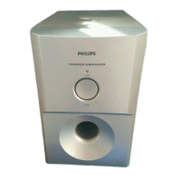
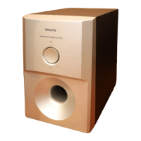
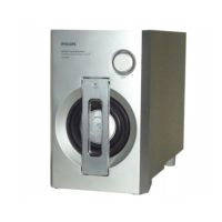
Steps to remove the grill base and speaker driver from the subwoofer box.

Front Assembly Dismantling

Procedure to carefully remove the front panel assembly of the subwoofer.

Rear Assembly Dismantling

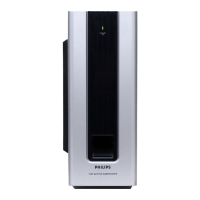
Instructions for removing screws to pull out the printed circuit board assembly from the rear.

Set Block Diagram

Set Wiring Diagram

Amplifier, I/P & LED/VR Boards

Internal IC Diagram

Internal block diagram illustrating the structure of the TDA7296 integrated circuit.

Circuit Diagram

Detailed schematic diagram showing the electronic components and their connections.

PCB Layout View

Visual representation of the component placement and routing on the printed circuit board.

Electrical Part List

Comprehensive list of electrical components with part numbers and specifications.

Exploded Drawing

Parts Lists

Mechanical & Accessories Parts

List of mechanical components and accessories with part numbers and descriptions.

Screw List

List of screws used in the main unit with specifications and quantities.

Related product manuals