Do you have a question about the Philips SW7000SA/00S and is the answer not in the manual?
Identifies the physical location of main printed circuit boards within the subwoofer.
Details the technical specifications of the active subwoofer, including output power and frequency response.
Outlines the recommended setup and equipment for performing measurements on the device.
Provides critical instructions for handling components safely and preventing electrostatic discharge.
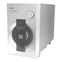
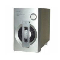
Procedure for safely removing the front grille assembly and the speaker driver.
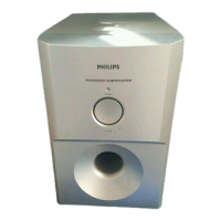
Steps for disassembling the front panel of the subwoofer.
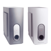
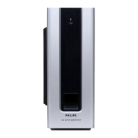
Procedure for disassembling the rear panel to access the circuit board assembly.
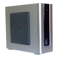
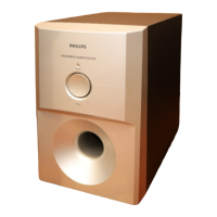
Illustrates the correct position of the subwoofer for servicing and repair.
High-level overview of the internal functional blocks of the active subwoofer.
Detailed schematic showing electrical connections between different boards and components.
Pin configuration and internal block diagrams for integrated circuits used on the board.
Schematic diagram detailing the electronic components and their interconnections on the board.
Visual representation of the component placement and routing on the printed circuit board.
List of electronic components required for the Amplifier, Input, and LED boards.
Specifies voltage measurements at key points for diagnostics in standby and operation modes.
Layout of the power board components, showing placement for 00S and 01S versions.
Schematic diagram for the power board, specific to the 00S version.
Schematic diagram for the power board, specific to the 01S version.
List of electronic components for the power board, including part numbers and specifications.
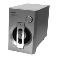
Visual representation of the subwoofer's components and their assembly order.
List of mechanical parts and accessories with part numbers for the subwoofer.
Details of screws used in the assembly, including size and type.