Service Modes, Error Codes, and Fault Finding
EN 26 Q529.1A LA5.
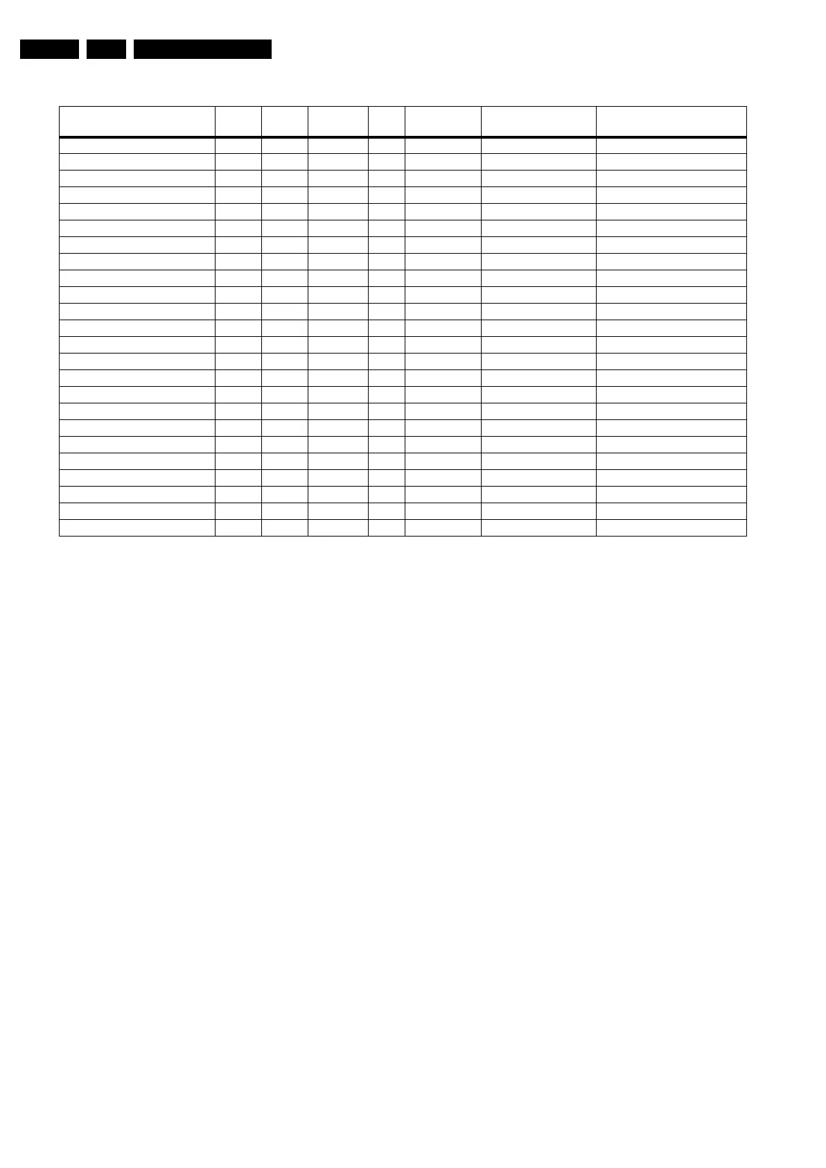
Table 5-2 Error code overview
Extra Info
• Rebooting. When a TV is constantly rebooting due to
internal problems, most of the time no errors will be logged
or blinked. This rebooting can be recognized via a ComPair
interface and Hyperterminal (for Hyperterminal settings,
see section “5.8 Fault Finding and Repair Tips, 5.8.6
Logging). It’s shown that the loggings which are generated
by the main software keep continuing. In this case
diagnose has to be done via ComPair.
• Error 11 (3V3/5V too high). This protection can occur
during start up (LAYER error 1 = 2). Be careful to overrule
this protection via SDM for the reason supply related
devices can be possibly destroyed here.
• Error 13 (I
2
C bus 3 blocked). At the time of release of this
manual, this error was not working as expected. Current
situation: when this error occurs, the TV will constantly
reboot due to the blocked bus. The best way for further
diagnosis here, is to use ComPair.
• Error 15 (PNX8541 doesn’t boot). Indicates that the main
processor was not able to read his bootscript. This error will
point to a hardware problem around the PNX8541
(supplies not OK, PNX 8541 completely dead, I
2
C link
between PNX and Stand-by Processor broken, etc...).
When error 15 occurs it is also possible that I
2
C2 bus is
blocked (NVM). I
2
C2 can be indicated in the schematics as
follows: SCL-UP-MIPS, SDA-UP-MIPS, SCL-2 or SDA-2.
Other root causes for this error can be due to hardware
problems with : NVM PNX5100, PNX5100 itself, DDR’s.
• Error 16 (12V). This voltage is made in the power supply
and results in protection (LAYER error 1 = 3) in case of
absence. When SDM is activated we see blinking LED
LAYER error 2 = 16.
• Error 18 (1V2-3V3-5V too low). All these supplies are
generated by the DC/DC supply on the SSB. If one of these
supplies is too low, protection occurs and blinking LED
LAYER error 1 = 2 will be displayed automatically. In SDM
this gives LAYER error 2 = 18.
• Error 19 (1V2 or class D). This is an combination of two
detections:
– If one of the 1V2 supplies is too high or too low in the
start up procedure the supply fault becomes low.
– If a DC voltage occurs on the output of the Class D
amplifier the supply fault becomes low. Be careful to
overrule this protection via SDM, check audio part first
before apply. In case one of the speakers is not
connected, the protection can also be triggered.
• Error 21 (PNX 5100). At the time of release of this manual,
this error was not working as expected. Current situation:
when this error occurs, the TV will constantly reboot. This
rebooting can be recognized via a ComPair interface and
Hyperterminal (for Hyperterminal settings, see section “5.8
Fault Finding and Repair Tips, 5.8.6 Logging”). It is shown
that the loggings which are generated by the main software
keep continuing. The best way for further diagnosis here, is
to use ComPair.
• Error 21 (PNX 5100). At the time of release of this manual,
this error was not working as expected. Current situation:
when there is no I
2
C communication towards the PNX5100
after startup (power off by disconnection of the mains
cord), LAYER error 2 will blink continuously via the blinking
LED procedure in SDM. (startup the TV with the solder
paths short to activate SDM).
• Error 23 (HDMI). When there is no I
2
C communication
towards the HDMI mux after start up, LAYER error 2 = 23
will be logged and displayed via the blinking LED
procedure if SDM is switched on.
• Error 26 (Master IF). When there is no I
2
C communication
towards the Master IF after start up, LAYER error 2 = 26
will be logged and displayed via the blinking LED
procedure when SDM is switched on.
• Error 28 (FPGA ambilight). When there is no I
2
C
communication towards the FPGA ambilight after start up,
LAYER error 2 = 28 will be logged and displayed via the
blinking LED procedure if SDM is switched on. Note that it
can take up several minutes before the TV starts blinking
LAYER error 1 = 2 in CSM or in SDM, LAYER error 2 = 28.
• Error 34 (Tuner). When there is no I
2
C communication
towards the tuner after start up, LAYER error 2 = 34 will be
Description Layer 1 Layer 2
Monitored
by
Error/
Prot
Error Buffer/
Blinking LED Device Defective Board
I
2
C3 2 13 MIPS E BL / EB SCL/D-SSB SSB
I
2
C4 5 14 MIPS E BL / EB SCL/D-DISP Display (LED back light only)
PNX doesn’t boot (HW cause) 2 15 Stby µP E BL PNX8541 I
2
C blocked SSB
12V 3 16 Stby µP P BL / Supply
1V2, 3V3, 5V to low 2 18 Stby µP P BL / SSB
1V2 or Class D 2 19 Stby µP P BL / SSB
3V3/5V DCDC to high 2 11 Stby µP P BL / SSB
PNX 5100 2 21 MIPS E EB PNX5100 SSB
HDMI mux 2 23 MIPS E EB AD8197A SSB
I
2
C switch 2 24 MIPS E EB PCA9540 SSB
Master IF 2 26 MIPS E EB TDA9898 SSB
FPGA Ambilight 2 28 MIPS E EB / SSB
Tuner 2 34 MIPS E EB UV1783S/TD1716 SSB
Channel Decoder DVB-T 2 37 MIPS E EB TDA10048 SSB
ST7100 2 38 MIPS E EB ST7100 SSB
MHP 6 39 MIPS E EB / MHP module
Fan I2C expander 7 41 MIPS E EB PCA9533 FAN module
T° sensor 7 42 MIPS E EB LM 75 T° sensor
FAN 1 7 43 MIPS E EB FAN
FAN 2 7 44 MIPS E EB FAN
main NVM 2 / MIPS E X STM24C128 SSB
Channel decoder DVB-C 2 48 MIPS E EB TDA 10023 SSB
PNX doesn’t boot (SW cause) 2 53 Stby µP E BL PNX8541 SSB
Display (only LED back light) 5 64 MIPS E BL / EB Display