Do you have a question about the Philips VSS2360 and is the answer not in the manual?
| Model | VSS2360 |
|---|---|
| Brand | Philips |
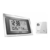
| Display | LCD |
| Indoor Temperature Range | 0°C to 50°C |
| Outdoor Temperature Range | -20°C to 60°C |
| Humidity Range | 20% to 95% |
| Wireless Transmission | Yes |
| Alarm | Yes |
| Transmission Range | 30 meters |
| Forecast | Yes |
Details general parameters like voltage, frequency, consumption, weight, dimensions, and temperature.
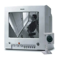
Outlines procedures for safe repair and maintenance of the monitor.
Step-by-step guide for taking apart the monitor casing.
Procedure for safely detaching the main internal panel from the monitor.
Describes the correct orientation for servicing the monitor.
Instructions for reassembling the monitor after repairs.
Electrical diagram for the µP and Power supply circuits.
Electrical diagram for the Deflection & Line output stages.
Electrical diagram for the Twisted Pair interface & Alarm output.
Electrical diagram for the Slave & Audio/Video interfaces.
Printed Wiring Board layout for component identification and placement.
General guidelines for controls and test signal setup before making adjustments.
Procedure to adjust the +24V power supply output to the specified voltage.
Adjusts the vertical size of the picture to match the horizontal size.
Rotates deflection coil and adjusts magnets for optimal picture geometry.
Tunes the coil for the correct carrier wave frequency for intercom communication.
Instructions for connecting cameras, VCR, extra monitors, and cables.
Details how to use monitor functions like system on/off, power save, brightness, volume, talk, and auto sequence.
Lists mechanical spare parts with their service codes and descriptions.