Do you have a question about the Philips VS23605T and is the answer not in the manual?
Details general specifications like mains voltage, frequency, power consumption, camera supply, weight, dimensions, ambient temperature, TV system, lines, field frequency, resolution-bandwidth, inputs, and outputs.
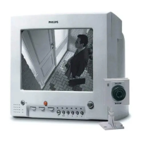
Describes controls and connections for POS models, referencing diagrams A-1 and A-2.
Details controls and connections for Retail models, referencing diagrams B-1 and B-2.
Details controls and connections for Slave models, referencing diagrams C-1 and C-2.
Outlines safety instructions for repairs, including using isolating transformers and replacing components.
Details safety regulations for repairs, component replacement, CRT handling, and electrical checks.
Provides general warnings about equipment handling, high-voltage hazards, and ESD precautions.
Addresses Electrostatic Discharge (ESD) precautions for handling semiconductors during repair.
Provides steps for disassembling the monitor and removing the main panel.
Describes the monitor's service position and reassembly process.
Guides troubleshooting for no intercom function or no audio/video present.
Details troubleshooting steps for EHT and deflection present faults.
Focuses on troubleshooting SMPS secondary and primary stages for faults.
Outlines troubleshooting for cases where there is no picture.
Presents the electrical diagram for circuit board A1, covering power supply and control sections.
Shows the electrical diagram for circuit board A2, covering deflection and line output stages.
Details the electrical diagram for circuit board A3, focusing on twisted pair interface and alarm output.
Presents the electrical diagram for circuit board A4, covering audio/video interfaces and buffer amplifiers.
Shows the Printed Wiring Board (PWB) layout, indicating component placement.
Details adjustments for the +24V supply and time base (frame amplitude).
Covers adjustments for picture geometry and carrier wave for intercom functions.
Guides users on installing the system, connecting cameras, VCR, and extra monitors.
Explains system on/off, power save, brightness, contrast, volume, talk, action, auto sequence, camera selection, and VCR mode.
Details alarm functions, programming, termination, priority, and maintenance tips like ventilation and cleaning.
Lists mechanical spare parts for VSS2360/00T, VS23605T, VS23655T models with service codes.
Lists mechanical spare parts for VSS2260/00R, 22MS605R, VS22605R models.
Lists mechanical spare parts for VSS4460/00T, VS44605T models.
Provides specific service information and solutions for potential system issues.
Documents changes made to the VM6 family, including part number updates and technical modifications.
Informs about service procedures for cameras VCM8637 and VCM8638, stating they are not repairable.
Provides corrections for the Service Manual regarding specific component types.
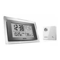
| Type | Wireless Weather Station |
|---|---|
| Display Type | LCD |
| Power Source (Indoor Unit) | 2 x AAA batteries (not included) |
| Alarm Function | Yes |
| Backlight | Yes |
| Indoor Temperature Range | 0°C to 50°C (32°F to 122°F) |
| Outdoor Temperature Range | -4°F to 140°F (-20°C to 60°C) |
| Humidity Range | 20% to 95% |
| Wireless Range | 100 feet (30 meters) |
| Features | Min/Max Records |
| Forecast Icons | Cloudy, Rainy, Sunny |