EasyManua.ls Logo

Philips VS23605T - Electrical and Mechanical Adjustments; Power Supply and Time Base Adjustments; Picture Geometry and Intercom Adjustments

Philips VS23605T
29 pages
Print Icon
To Next Page IconTo Next Page
To Previous Page IconTo Previous Page
Loading...
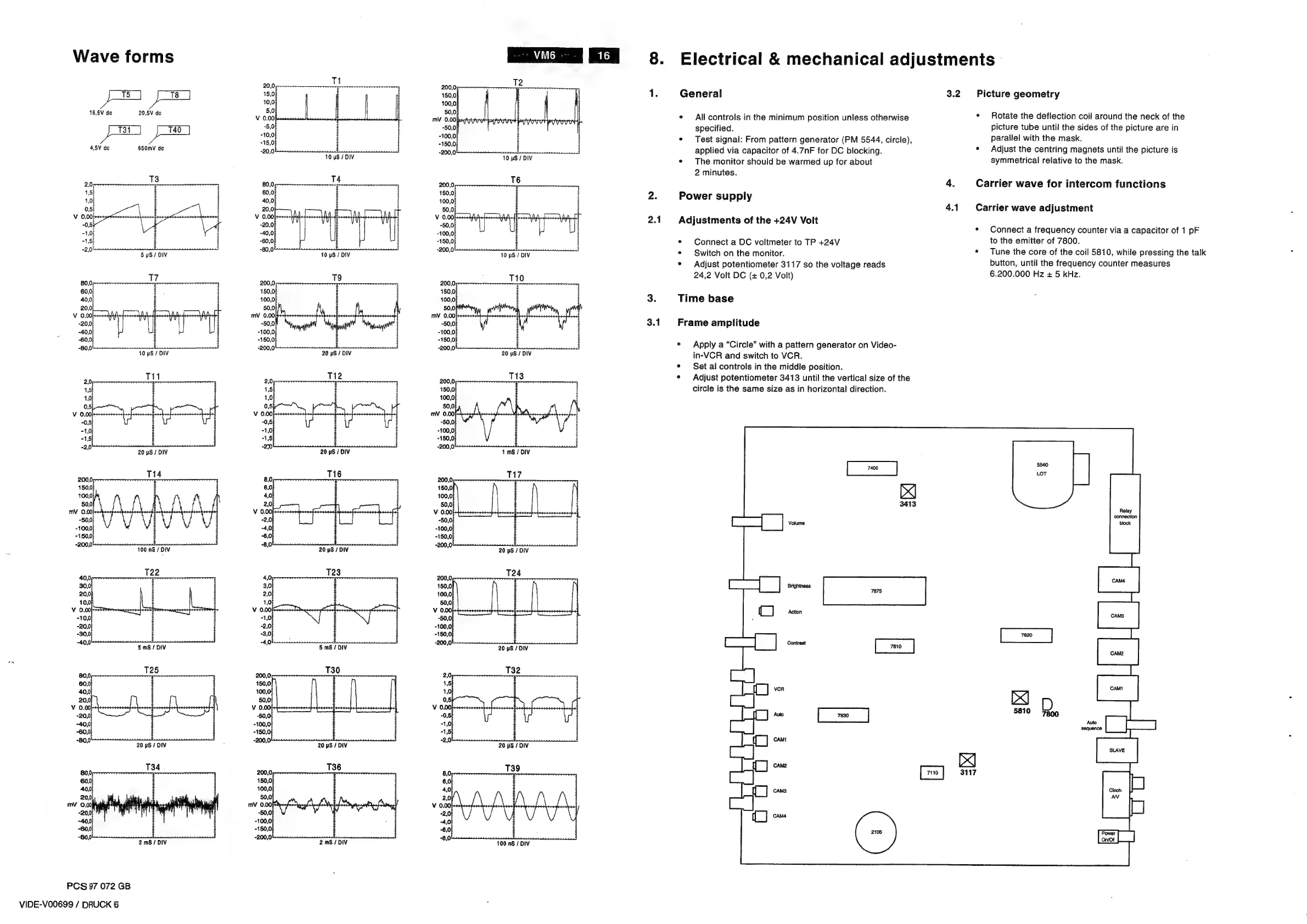
Wave
forms
VG
20,0,
sl
FS
pe
is0
10,0
16,5V
de
20,8V
de
5.0
V
0.00
-5,0
pao
10,0
-15,0
4,5V
de
650mV
de
-20,0
-
10
wS/
DIV
;
10
pS
/
DIV
80,0
60,0
40,0)
20,0)
V
0.00)
-20,0
-40,0
60,0
-80,0
5
pS
/
DIV
10S
/
DIV
e080
10
pS
/
DIV
:
20
uS
/
DIV
26
Ti1
20
M2
200,0,
is
15
1,5
r
1,0
1,0
,
05
05
V
0.00
V
0.00
.
-0,5)
-0,5|
-50,
-1,0
-1,0)
-100,
-15
1,5
K
ae
20
uS
/
DIV
sd
20
wS
/
DIV
:
1
mS
/
DIV
2000
T14
a0
T16
508
T17
150.0
6,0
150,0|
100,0
4,0
100,0|
50,0)
2,0
50,0
mV
0.00
V
0.00)
V
0.00)
-500
-2,0
-50,0
-100,0
-4,0)
-100,0
-150,0
-6,0)
-150,0
"ene
100
nS
/
DIV
ve
20
yS
/
DIV
ore
20
pS
/
DIV
2600
T24
150,0
100,0
50,0
V
0.00)
k
-50,0)
-20,
-100,0
-30,
+150,
3800
5
mS
/
DIV
:
5
mS/DIV
me
20
yS
/
DIV
_
125
ead
730
29
ue
60,0
150,0|
15
40,0
100,0)
1,0
20,00
50,0
05
V
0.00
V
0.00
V
0.00)
-20,0) -50,0)
-0,5)
-40,0
-100,0}
“1,0
-60,0)
-150,0
“1,5
“S08
20
pS
/
DIV
;
2m.
20
yS
/
DIV
as
20
yS
/
DIV
ae
T34
AY
T39
600
6,0
400
40
200
2,0
mV
0.00
V
0.00)
-20,)
-2,0
40,0)
-4,0)
-600
6,0)
oat
2mS/DIV
.
2mS/DIV
a8
100
nS
/
DIV
PCS
97
072
GB
VIDE-VO0699
/
DRUCK
6
8.
2.1
3.1
Electrical
&
mechanical
adjustments
General
3.2
¢
All
controls
in
the
minimum
position
unless
otherwise
specified.
¢
Test
signal:
From
pattern
generator
(PM
5544,
circle),
applied
via
capacitor
of
4.7nF
for
DC
blocking.
¢
The
monitor
should
be
warmed
up
for
about
2
minutes.
Power
supply
4.1
Adjustments
of
the
+24V
Volt
¢
Connect
a
DC
voltmeter
to
TP
+24V
¢
Switch
on
the
monitor.
¢
Adjust
potentiometer
3117
so
the
voltage
reads
24,2
Volt
DC
(+
0,2
Volt)
Time
base
Frame
amplitude
¢
Apply
a
“Circle”
with
a
pattern
generator
on
Video-
in-VCR
and
switch
to
VCR.
¢
Set
al
controls
in
the
middle
position.
¢
Adjust
potentiometer
3413
until
the
vertical
size
of
the
circle
is
the
same
size
as
in
horizontal
direction.
7110
Picture
geometry
¢
Rotate
the
deflection
coil
around
the
neck
of
the
picture
tube
until
the
sides
of
the
picture
are
in
parallel
with
the
mask.
¢
Adjust
the
centring
magnets
until
the
picture
is
symmetrical
relative
to
the
mask.
Carrier
wave
for
intercom
functions
Carrier
wave
adjustment
¢
Connect
a
frequency
counter
via
a
capacitor
of
1
pF
to
the
emitter
of
7800.
*
Tune
the
core
of
the
coil
5810,
while
pressing
the
talk
button,
until
the
frequency
counter
measures
6.200.000
Hz
+
5
kHz.
3117