PHONIC CORPORATIONA6500 USER’S MANUALPage 6
14. HI COMP. RAT control
This control knob determines the compression
ratio for the high band, ranging from 1:1.2 to
1:25.
15. (High) ATTACK control
This control knob determines the speed with
which the compression for the high band
begins after the input level has exceeded the
threshold. The range of control is from 0.1 to 200
milliseconds.
16. (High) RELEASE control
This control knob determines the speed with
which the compression for the high band
ceases after the input level has fallen below the
threshold. The range of control is from 0.05 to 3
seconds.
17. OUT LEVEL control
This control knob adjusts the level of the
channel output. The range of control is from -12
to +12 dB.
18. BYPASS button
This toggle button determines whether the signal
from the channel input should be processed
(released) or unaltered (depressed) before it is
sent to the channel output. The bypass function is
useful for a quick comparison between processed
and unprocessed sounds.
19. CH. LINK button
This toggle button determines whether Channel
1 and Channel 2 are to be controlled separately
(released) or in sync (depressed). When the
button is depressed, the settings for Channel 1
are applied to both channels.
20. POWER button
This toggle button turns on the OPTIMIZER when
depressed, and turns it off when released.
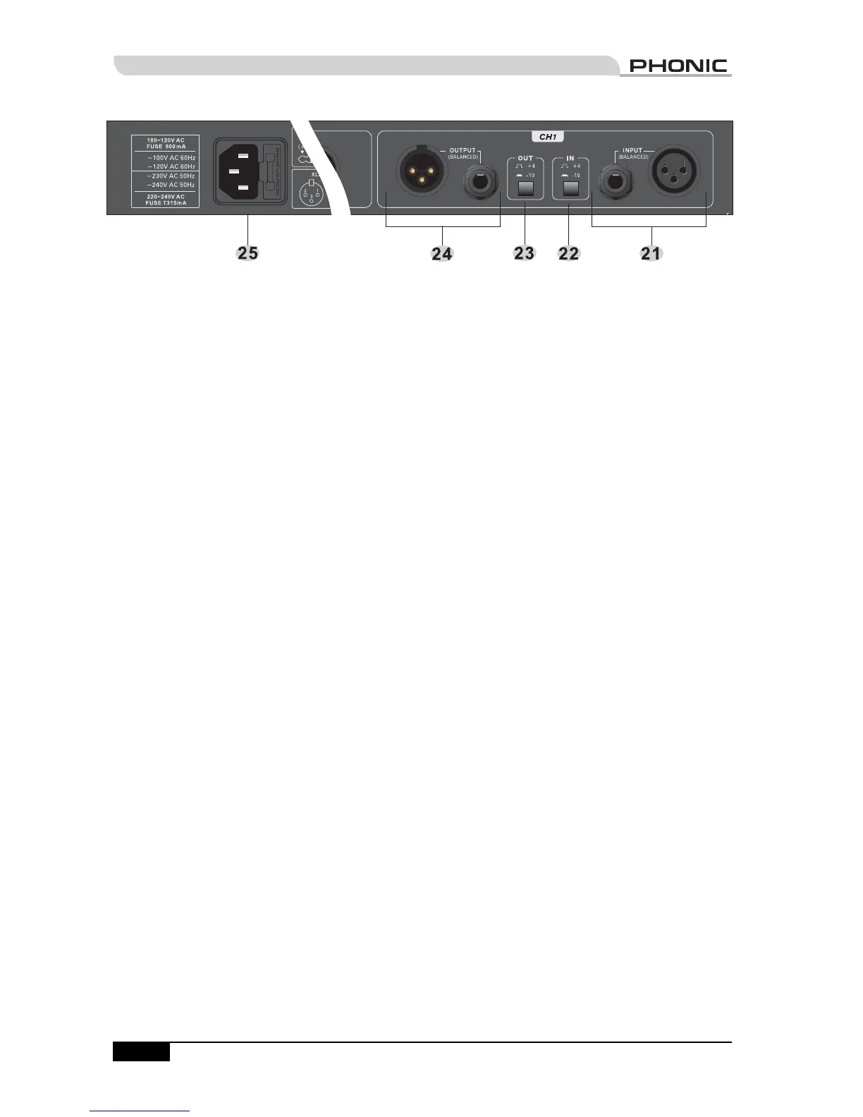
Back Panel
21. INPUT connectors
The input connection is equipped with a female
XLR and a 1/4" TRS jack. Both connectors are
balanced.
22. Nominal operating level (IN)
This toggle button determines the nominal
operating level of the input (-10 dBV when
depressed, and +4 dBu when released). This
setting should match the nominal operating
level of the source device. In general, consumer
products use -10 dBV, while professional
products use +4 dBu.
23. Nominal operating level (OUT)
This toggle button determines the nominal
operating level of the output (-10 dBV when
depressed, and +4 dBu when released). This
setting should match the nominal operating
level of the target device. In general, consumer
products use -10 dBV, while professional
products use +4 dBu.
24. OUTPUT connectors
The output connection is equipped with a male
XLR and a 1/4" TRS jack. Both connectors are
balanced.
25. Power inlet and fuse holder
Use the supplied power cord to connect the
OPTIMIZER to an AC power outlet of a suitable
voltage. To change the fuse, use a screwdriver to
slide open the fuse cover, then replace the fuse
with one that is of identical type.
CONTROLS & CONNECTIONS
 Loading...