PHONIC CORPORATION
Page 6 P(A)450/550 USER
’
S MANUAL
PA450 / 550
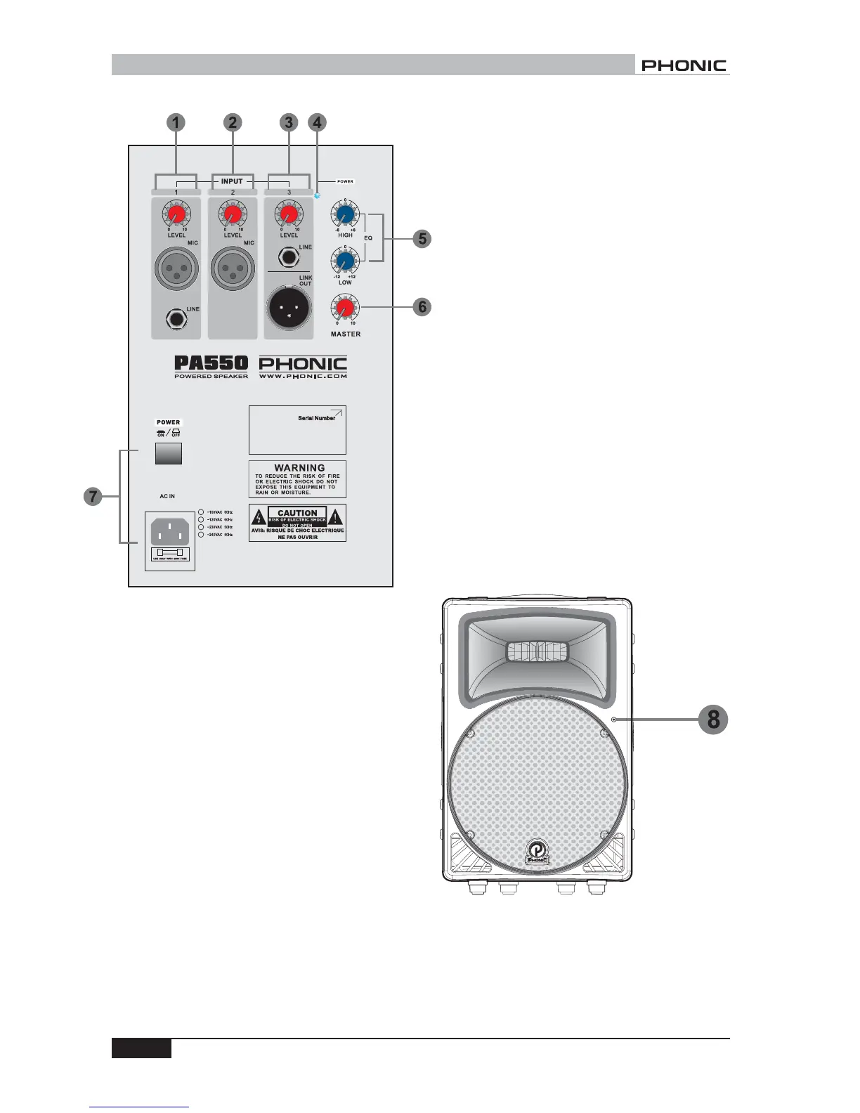
1. INPUT 1
A balanced XLR connector for microphone, and a
balanced 1/4" phone jack for line input source pro-
vide flexible connection for different kinds of input
sources. A level control adjusts the final level of the
input from INPUT 1.
2. INPUT 2
INPUT 2 comes with one balanced XLR connector
for microphone input. There is a built-in low cut
filter in the signal path of INPUT 2 for eliminating
stage rombling. A level control adjusts the final level
of the input from INPUT 2.
3. INPUT 3
INPUT 3 comes with one 1/4" phone jack for line
source. A level control adjusts the final level of the
input from INPUT 3. One link out XLR connector is
also provided for connecting to another PA550/450
or speaker system as chain arraying.
4. POWER INDICATOR
This red LED indicator light up whenever the power
in being turned on.
5. EQ OCNTROL
High frequency level control provides a boost or cut
of 6dB for tweeter output. Low frequency level
control provides a boost or cut of 12dB for woofer
output. Turn the control clockwise to boost the level,
counter-clockwise to cut it.
6. MASTER LEVEL CONTROL
This control enables you to adjust the total volume
level.
7. POWER SWITCH AND AC IN CONNECTOR
Connect the included power cord into the connector
before pressing on the switch to turn on the system.
Both LED indicators in the back and in the front will
light up.
8. POWER /OVERLOAD INDICATOR
This bi-color indicator at the right-hand side of front
panel light up in green when power is being turned
on, in red when overload happens.
PA450/550 ACTIVE VERSION