“ASSEMBLE INSTRUCTIONS”
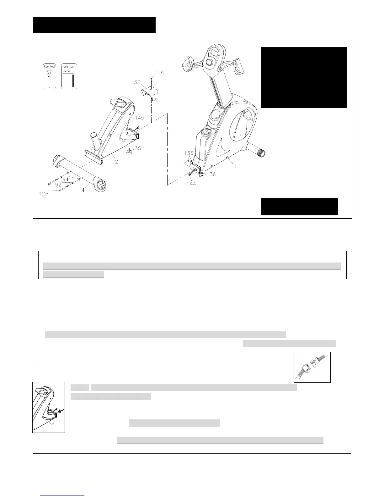
STEP 4 –
Rear Stabilizer Assembly
a. Attach the Rear Stabilizer (4) to the Rear Support Frame (2).
b. Fully secure two Lock Washers (M8)(92), two Washers (8x16x2.0t)(94) and two Bolts, Socket Head
(M8xp1.25x90mm)(126) that attach to the Rear Stabilizer (4) to the Rear Support Frame (2).
STEP 5 –
Rear & Main Frame Assembly
a. Thread the Leveler (35) tightly into the Rear Support Frame (2).
To make the Leveler (35) rest firmly on the floor, please review page 13 on the manual.
b. Connect the Pulse Sensor Wire 3 (145) to the Pulse Sensor Wire 2 (144). Be careful not to pinch the wires.
NOTE: Four Nylock Nut (M8xp1.25)(136) will be pre-attached on the front of the Rear
Support Frame Assembly (2)
c. Remove four Nylock Nut (M8xp1.25)(136) from the front of the Rear Support Frame Assembly (2)
d. Attach the Rear Support Frame Assembly (2) to the Main Frame (1) by securing four Nylock Nut
(M8xp1.25)(136). Be careful not to pinch the wires
e. Attach the Connection Cover (33) to the Main Frame (1) by securing Screw, Round Head
(M5xp0.8x40mm) (108). **Make sure the above parts are tightened before moving on to the next page**
NOTE: “Small Tip: Attach screws and bolts to the assembly parts first before secure”
**Please do not secure the bolts unless you make sure Bolts all go into screw holes of Rear Stabilizer and
Rear Support Frame**
NOTE: After connecting the wires’ pins, slightly and gently pull two sides of wires to test and
make sure whether the wires are fully connected.
 Loading...