Do you have a question about the PI 2 Design PI2AES and is the answer not in the manual?
The PI2AES conforms to specifications for Dimensions, Weight, Storage/Operating Temperature, Humidity, Input Voltage, and Power Consumption.
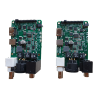
The PI2AES is a professional I/O Shield bringing Studio Grade Audio to Raspberry Pi family of computers.
Provides a block diagram illustrating the PI2AES Shield's architecture and component interconnections.
Details the devices located on the PI2AES, which interfaces to the RPi via the 40-Pin GPIO Connector.
Describes the CPU I2C Bus usage for PI2AES devices, with addresses typically set by the startup script.
Focuses on the WM8804 chip, the core AES Digital Audio Transmitter, interfacing via I2S and I2C.
Provides important notes regarding WM8804 control, Master mode operation, and GPIO clock selection.
Details the pair of NDK NZ2520SD Ultra-Low Noise clocks providing critical timing signals for the WM8804.
Explains the RS-422 Differential Transmitter that sends SPDIF output to the XLR connector.
Describes the 74FCT125 CMOS Buffer used to drive I2S signals to the I2S Expansion Header.
Covers the DS2063 Quad Differential LVDS Driver for converting I2S Bus signals to HDMI.
Details the triple stack LED indicators for Power ON, 48/96/192Khz Audio Data Rate, and 44.1/88.2/176.4Khz Clock Base.
Introduces the usage of RPi GPIO header signals for control and status purposes on the PI2AES.
Provides essential notes on RPi GPIO DIR, Alternate Function (AF), and Pullup/Pulldown (PUP/PDN) resistor configurations.
Explains the PI2AES power design, including external +12V to +48V source and RPi power via jumper W2.
Discusses the necessity of initializing CPU registers and devices for PI2AES operation, directing to online resources for code.
Introduces the section detailing the type, location, and pinout of various connectors on the PI2AES board.
Describes the DC Jack for external power input, specifying the plug type and acceptable voltage range.
Details the standard 40-Pin GPIO Header, crucial for interfacing the PI2AES with the Raspberry Pi.
Covers the 16-Pin I2S Expansion Header, which carries I2S, I2C, and Power signals for external use.
Details the P3 3-Pin XLR Connector, used for balanced digital audio output with 100-ohm impedance.
Explains the P4 HDMI Connector for Differential I2S signal transmission, compatible with PS Audio or Gustard standards.
Describes U9, a component providing RCA for AES COAX and Toslink for SPDIF Optical digital audio outputs.
Details the D1 triple LED indicators for Power Status and Audio Data/Clock Base rates.
States that there are currently no known errata for the PI2AES Rev. P1.
| Type | Digital Audio Interface |
|---|---|
| Word Clock Output | Yes |
| Sample Rates | 44.1kHz, 48kHz, 88.2kHz, 96kHz, 176.4kHz, 192kHz |
| Maximum Sample Rate | 192kHz |
| Output | AES/EBU, TOSLINK |
| I2S Output | Yes |
| Bit Depth | 16-bit, 24-bit |
| Power Supply | 5V DC |