PI2Media PI2AES Hardware Reference Manual – P0.1 - 3/27/2019
PAGE 9
5
55
5 R
RR
RPI
PI PI
PI GPIO
GPIOGPIO
GPIO
5.1 OVERVIEW
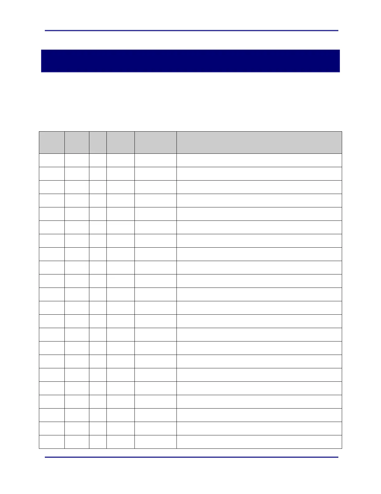
The PI2AES uses a number of signals from the RPi GPIO header for control and status
purposes. This usage is defined in the following table.
RPi
PIN
DIR AF
PUP/
PDN
PI2AES
Name
Description/Notes
1 - - - - RPi +3.3V - Unused
2 - - - +5V +5V Power to/from the RPi
3 I/O Y PUP I2C_SDA I2C Bus Data
4 - - - +5V +5V Power to/from the RPi
5 OUT Y PUP I2C_SCL I2C Bus Clock
6 - - - GND
7 OUT - - GPIO4 Unused
8 - - - GPIO14 Unused
9 - - - GND Unused
10 - - - GPIO15 Unused
11 - - - GPIO17 Unused
12 IN Y - BCLK I2S Bit Clock from WM8804
13 - - - GPIO27 Unused
14 - - - GND
15 - - - GPIO22 Unused
16 - - - GPIO23 Unused
17 - - - - RPi +3.3V - Unused
18 - - - GPIO24 Unused
19 - - - GPIO10 Unused
20 - - - GND
21 - - - GPIO9 Unused
22 - - - GPIO25 Unused