PICK VARIABLE FLOW SERVICE MANUAL
13
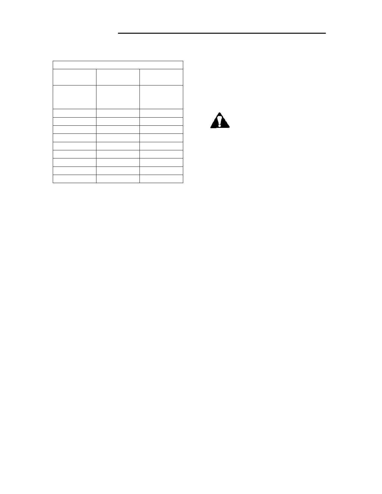
TABLE 2
Size and QTY of Injection Tube Fasteners
Heater
Model
Bolt Size Quantity
6X7 ¼-28
Shoulder
Bolt
1
6X10 ¼-28 x 5/8 3
6X25 “ 4
6X50 ¼-28 X 3/4 5
6X75 “ 6
6X100 “ 6
6X150 “ 12
6X200 “ 12
6X350 “ 12
6X500 “ 18
HEATER DISASSEMBLY- GENERAL
INSTRUCTIONS
Note: These instructions assume the heater
is installed in the vertical-up flow
orientation.
1. Shut down the heater by closing the
air supply to the temperature
controller.
2. Shut off the pump, and disconnect
the electric power.
3. Close the manual steam supply
valve.
4. Cool the heater if hot, by running
cold water through it. Close the cold
water supply valve.
IMPORTANT: Be sure the steam and
water lines are shut off completely
5. Close the water outlet valve (make a
note of its position when open) to
prevent draining of the distribution
system.
6. Drain all water from the heater by
opening the drain valves under the
pump and heater.
DISASSEMBLY OF MODEL 6X10
THROUGH 6X500
1. Remove the heater housing bolts.
2. Disconnect the union in the
horizontal outlet piping on threaded
units. On welded assemblies remove
the outlet assembly between heater
and outlet valve.
3. Carefully remove the outlet housing,
lifting it straight up until it is
completely clear of the injection
tube. SEE FIGURE 3
CAUTION: The weight of the
outlet housing is listed in the
table shown in FIGURE 1. To
avoid injury, provide mechanical
assistance when handling housing.
IMPORTANT: A minimum clearance
above the heater body at least equal to
dimension ‘D’ in FIGURE 1 must be
available to remove the outlet housing.
Life the outlet housing straight up, using
care to prevent accidental contact
between the housing and the injection
tube during lifting, damage to the
injection tube may result.
REMOVING THE INJECTION TUBE
The injection tube is machined to close
tolerances and is threaded into the inlet
housing. It can be removed with a pipe
wrench or chain wrench. Place the wrench
over the rivets near the threaded end of the
tube. If additional force is required, a second
wrench can be applied over the bolts holding
the spring stopper, at the opposite end of the
tube. SEE FIGURE 3.
IMPORTANT: To avoid damaging the
injection tube, apply the wrench on the
rivet area only. Do not apply the wrench
to the area containing orifices, i.e.,
between the rivets and spring stopper
retaining bolts.
DISASSEMBLY AND INSPECTION OF
THE MODEL 6X7 HEATER
The body of the 6X7 heater consists of a
single housing. See Figure 4