Page 2.2
LXI 7-SLOT MODULAR SWITCHING CHASSIS 60-102C
pickering
SECTION 2 - TECHNICAL DESCRIPTION
FUNCTIONAL DESCRIPTION
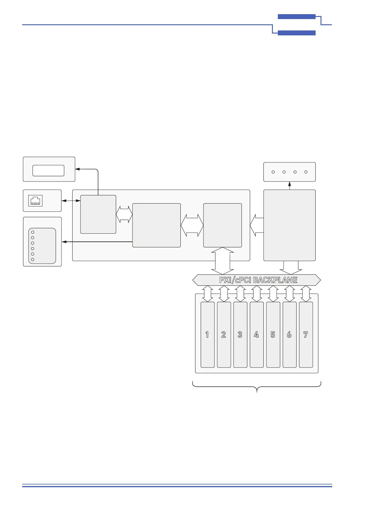
The 60-102C LXI Chassis is capable of supporting a wide range of PXI switching cards in a self-contained unit,
the only connections required are power and an Ethernet lead. The chassis consists of a 7-slot PXI/compactPCI
compatible backplane and a controller card with power being supplied from an internal mains power unit. Control
and programming information for the PXI modules installed in the chassis is sent to the backplane via a PCI bridge
device on the controller card. Programming information for the controller is sent to the chassis via the LAN interface
from a remote computer using the chassis unique Ethernet address. Programming documentation for the chassis as
well as data for Pickering’s LXI compatible switching products is stored in the embedded processor on the controller
card and can be downloaded over the LAN interface. LXI Status LEDs on the front of the chassis indicate condition
of the LAN interface. The status of the chassis power supply rails are indicated on four front panel LEDs.
Power
Supply
PCI
Bridge
LAN
Interface
PWR
RDY
ERR
LAN
LXI Status LEDs
RJ45
Socket
Embedded
Processor
PXI/cPCI BACKPLANE
3U PXI Module Slots
1 2 3 4 5 6 7
Controller Card
IP Address Display
100BaseT
1000BaseT
Voltage Status LEDs
+12V+5V+3.3V -12V
Figure 3.1 - Block Diagram for the 60-102C Seven Slot LXI Chassis
 Loading...