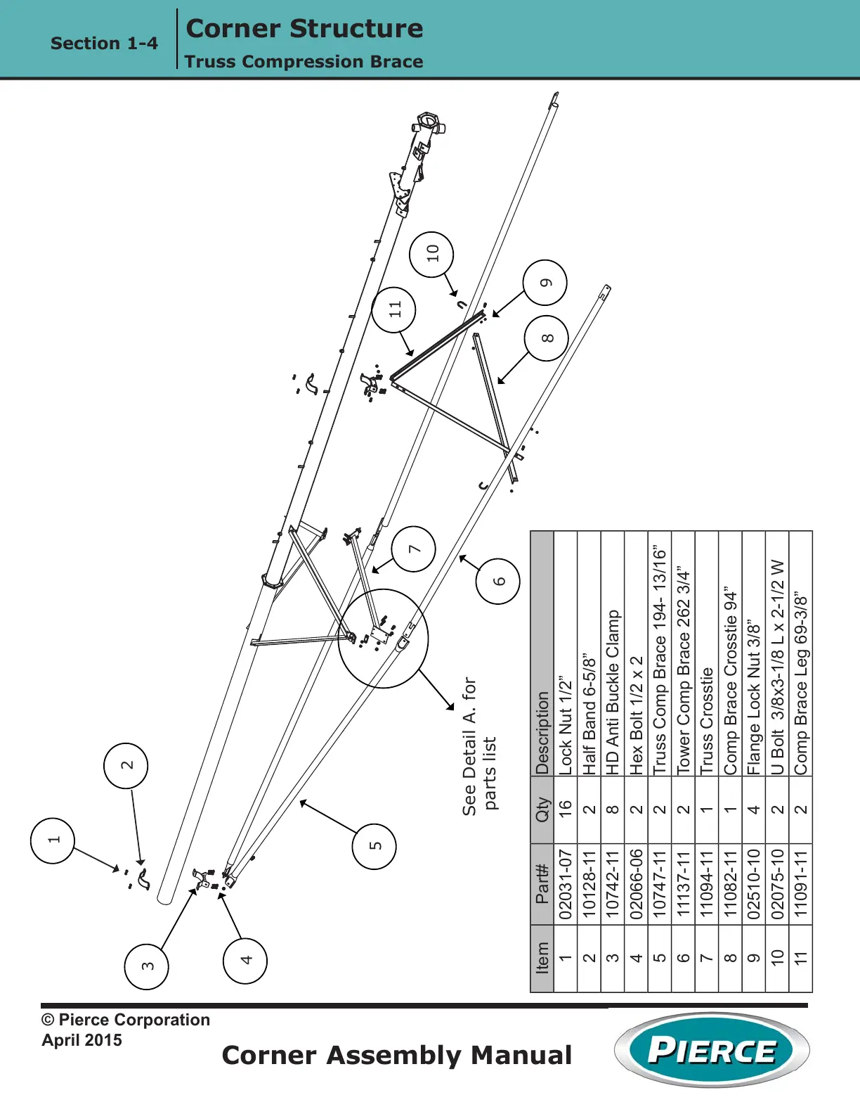
Corner Structure
Corner Assembly Manual
Section 1-4
© Pierce Corporation
April 2015
Truss Compression Brace
1
2
3
4
5
6
7
8
9
10
11
See Detail A. for
parts list
Item Part# Qty Description
1 02031-07 16 Lock Nut 1/2”
2 10128-11 2 Half Band 6-5/8”
3 10742-11 8 HD Anti Buckle Clamp
4 02066-06 2 Hex Bolt 1/2 x 2
5 10747-11 2 Truss Comp Brace 194- 13/16”
6 11137-11 2 Tower Comp Brace 262 3/4”
7 11094-11 1 Truss Crosstie
8 11082-11 1 Comp Brace Crosstie 94”
9 02510-10 4 Flange Lock Nut 3/8”
10 02075-10 2 U Bolt 3/8x3-1/8 L x 2-1/2 W
11 11091-11 2 Comp Brace Leg 69-3/8”
 Loading...