CP600 Pivot Operators Manual
OPERATION, SAFETY & MAINTENANCE
Section 1-12
© Pierce Corporation
July 2010
Note: The following maintenance procedures must be performed or the drivetrain
warranty will be void.
The fi nal drive wheel gearbox, center drive gear motor and the worm gear center drive require pre-
season maintenance. Please refer to the following service information for the above items.
If you should have any questions, please call your Pierce Dealer or Customer Service Representa-
tive.
FINAL DRIVE GEARBOX MAINTENANCE PROCEDURES
A. The fi nal drive gearbox must be serviced as follows after each crop cycle:
1. Inspect input and output shaft seals for leakage. Should either the input or out
put shaft show excessive leakage, the seals should be replaced. All replaced
seals must be installed with generous amounts of #2 Barium/Lithium based grease
or use equivalent quality #2 water-resistant grease.
2. External (dust exclusion) seals should be used to keep dirt and water out of inter-
nal seal locations. If the external seals are damaged or worn, replace with new
seals.
3. The seal drain hole located on both input caps must be kept clear of dirt. Clear the hole
with a 12-gauge wire, nail or punch. Rotate the tool to loosen and remove dirt. Make sure the
vent hole in the expansion chamber is free of dirt or debris.
Power Drivetrain Maintenance
Power Drivetrain Maintenance
Figure 1-10.
File: ams_srvc_0199.doc
Copyright 08/2004
I - FINAL DRIVE GEARBOX MAINTENANCE PROCEDURES
A. THE FINAL DRIVE GEARBOX MUST BE SERVICED AS FOLLOWS AFTER EACH CROP
CYCLE, A MINIMUM OF ONCE A YEAR.
SEE SECTION “
V
” “TOW HUB MAINTENANCE” FOR 725-UT TOWABLE
GEARBOXES.
SEE SECTION “D” AND “E”
FOR ADDITIONAL REQUIREMENTS FOR TNT AND 760
MODELS.
1. Inspect input and output shaft seals for leakage. Should either the input or output shaft seals show
excessive leakage, the seals should be replaced. All replaced seals must be installed with
generous amounts of #2 Barium/Lithium base grease (or use equivalent quality #2 water resistant
grease) on the seal lips.
2. External (dust exclusion) seals should be used to keep dirt and water out of internal seal locations.
If the external seals are damaged or worn, replace with new seals. Note that there are several
different types of seals available.
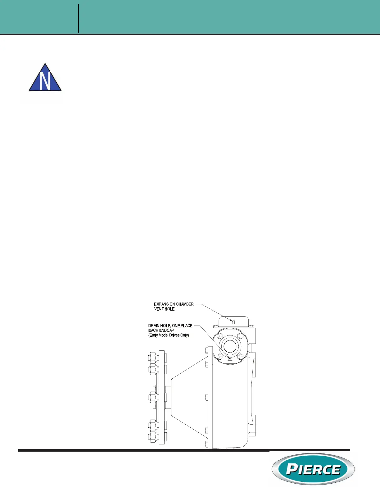
3. The seal drain hole (on 720 and previous models and on 725 units shipped before October
1996) located on both input caps must be kept clear of dirt. Clear the hole using a 12-gauge wire,
a nail or a punch. Lightly rotate the tool to loosen and remove dirt. CAUTION, DO NOT DAMAGE
THE SEAL CASE OR LIPS. See Diagram FD-1.
4. The vent hole located on the side of the Expansion Chamber must be kept clear of dirt. Use a soft
brush to clear the opening. DO NOT INSERT ANY OBJECTS INTO THE VENT HOLE,
DAMAGE TO THE RUBBER DIAPHRAGM MAY OCCUR.
DIAGRAM FD-1
 Loading...