2mm
Screw (2x10mm)
Washer (2x5mm)
Nut (2mm )
Washer (2x5mm)
2
Screw (2x10mm)
Washer (2x5mm)
4
2
Nut (2mm )
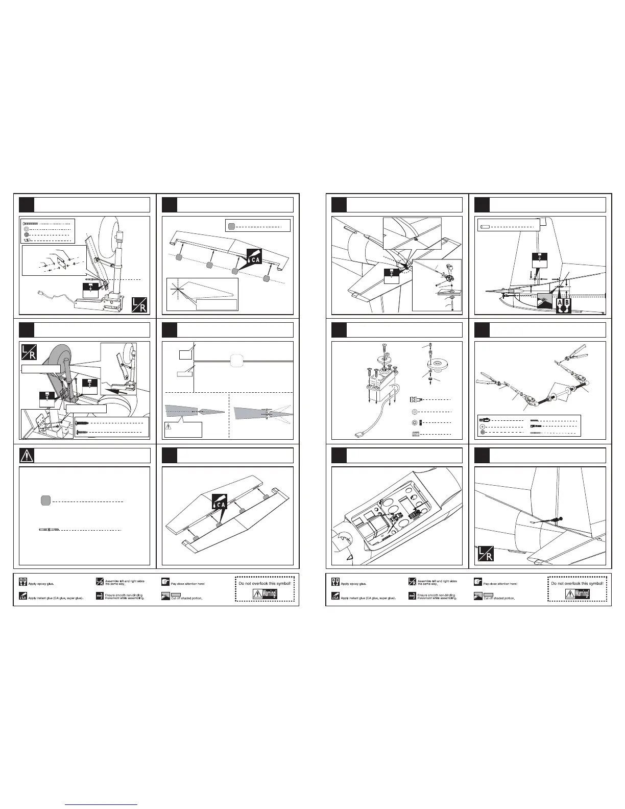
Assemble one part of the pin hinge to
the baffle with screw as illustration.
1.5mm
1.5mm
4
TP Screw (2.3x12mm)
TP Screw(3x20mm)
8
TP Screw(3x20mm)
TP Screw (2.3x12mm)
Assemble another part of the pin hinge to the mid wing
and assemble the retract to the mid wing with screw.
3
Pin hinge(2.5x48mm)
Apply instant type CA glue to elevator and pin hinge.
1mm
Elevator
Tailing
edge
Make sure they are in
the right position while
installing.
Keep some space about 1mm width between
elevator and tailing edge.
Make sure hinges are
mounted in the same line.
4
Pin hinge(24x24mm)
4
Pin hinge(24x24mm)
Glue the elevator to the stabilizer by CA and epoxy.
2
Pin hinge (36x20x1mm)
3
Pivot & round hinges
6
31
30
29
27
28
Accessory list for the coming installation steps.
3mm
Rod (2x200mm)
Clevis
Washer(3x15mm)
Washer
Lock Nut (3mm )
Screw (3x35mm)
Linkage Stopper
Washer (2mm)
Washer (2mm)
Nut (2mm)
Set screw (3x4mm)
Washer (
2mm
)
Set screw (3x4mm)
1
1
1
1
2
Steel wire (0.5x3000mm)
2
2
2
Clevis
Washer(3x15mm)
Lock Nut (3mm )
1
Screw (3x80mm)
2
Copper joiner
Washer(3x15mm)
Screw (3x80mm)
Lock Nut (3mm )
Clevis
Aluminum tube
Steel wire
The sketch map after the rudder shaft assemble finished.
30mm
10mm
100mm
3mm
2
Plastical tube(3x30mm)
Plastical tube(3x30mm)
Install the elevator servo.
Assemble the elevator servo to appropriate position
in the fuselage.
Drill small holes to appropriate position in the rudder and
the fuselage as below, epoxy the plastical tube to the hole
in the fuselage.
The sketch map after connect the rudder servo and the
rudder via the rudder shaft and the steel wires.
Connecting the elevator servo and the elevator.
11
58
56
53
54
55
57
 Loading...