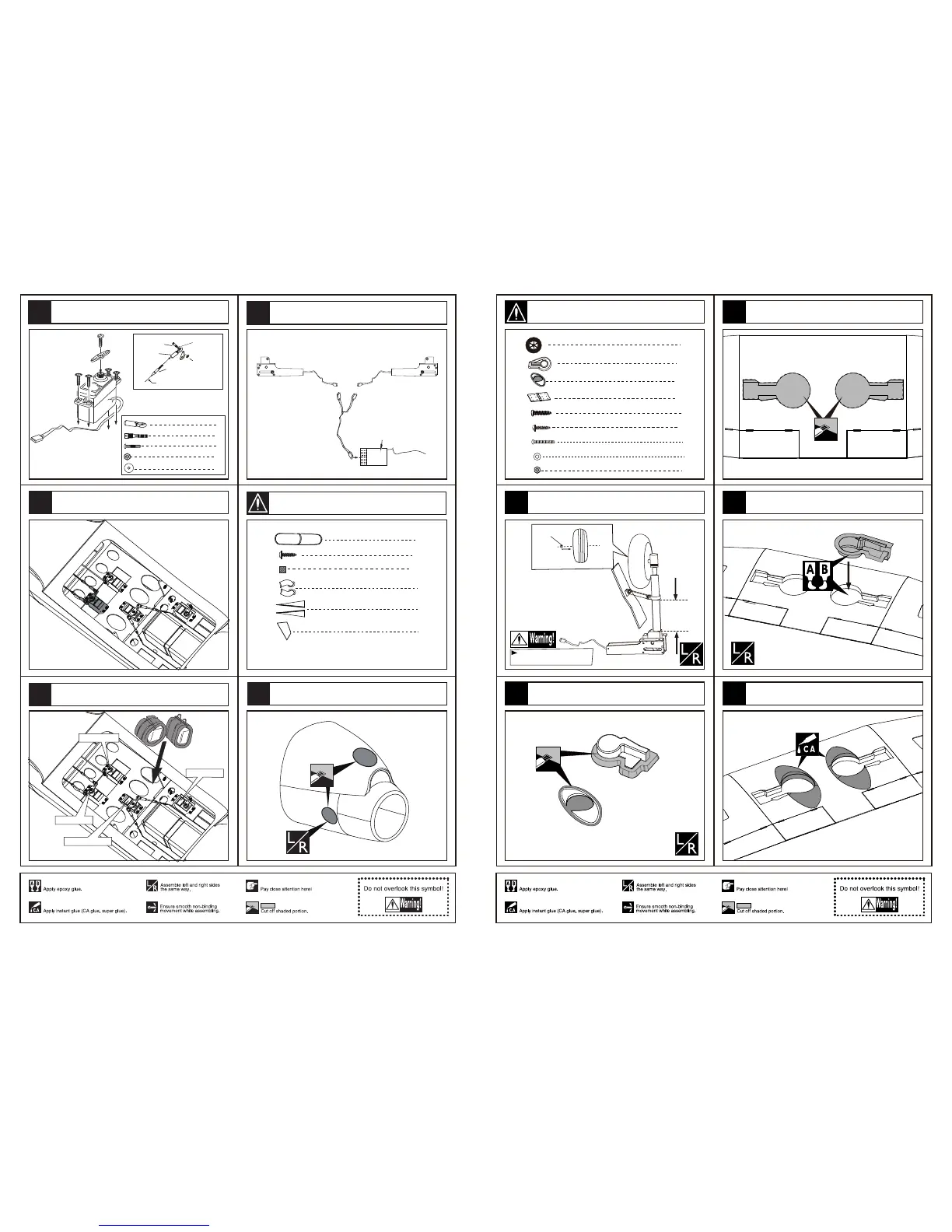
Cut away the film on the position for the air retract
landing and epoxy the wheel house to relevant position.
LockNut(4mm)
inside
Note:rubber wheels oleo struts
and retracts are optional.
Appropriate
position
Assemble the wheel and the baffle to the landing gear.
Cut off the surplus PVC part carefully along
the shaded line
Trim the shaded portion covering off the mid wing carefully.
2
Wheel (90mm)
2
PVC
2
PVC
2
Pin hinge (36x20x1mm)
4
TP Screw (2.3x12mm)
TP Screw(3x20mm)
8
2
Screw (2x10mm)
Washer (2x5mm)
4
2
Nut (2mm )
Glue the decoration PVC part around the wheel well.
5
25
26
24
23
22
Accessory list for the coming installation steps.
10
TP Screw (2.3x8mm)
1
Canopy
Ply (15x15x3mm)
10
2
Exhaust
1
Decoration
1
Decoration
4
4
Clevis
Copper joiner
4
4
Screw (2x10mm)
Nut (2mm )
4
Washer(2x5mm)
Steel wire
Copper joiner
Lock Nut (2mm )
Screw (2x10mm)
Ball joint
Washer(2x5mm)
Throttle servo
Nose wheel servo
Trim the cowling along the shaded line.
Install the rudder servo.
Assemble the rudder servo to appropriate position
in the fuselage.
Mount the receiver and the battery in the fuselage.
The sketch map when the servos install completion.
Elevator servo
Rudder servo
Receiver
Connect the electric retract & receiver as illustration below.
12
62
61
63
59
60
Accessory list for the coming installation steps.