18
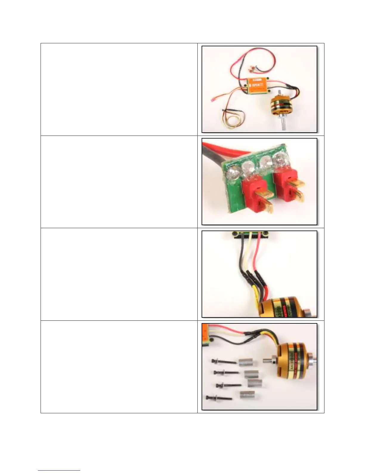
53. Assemble your power system per
manufacturer’s instructions. This is the
recommended setup below. Install a 6”
servo extension to the throttle control lead of
the ESC (black connector for Jeti SPIN) and
wrap connector with tape or heat shrink
tubing.
54. Solder a Deans Series connector onto
speed control and cover exposed solder
joints with PFM or Clear Silicon.
55. Connect the wires as shown for the stock
setup. This allows motor to turn correct
direction.
56. Prepare to install the motor, ESC, and
aluminum standoffs. For the standard setup,
use the 1” (25mm) spacers and the 1-1/2”
(40mm) Cap head screws, lock washers,
and large washers as shown.


 To Next Page
 Loading...