This document provides a service manual for the Pioneer Stereo Amplifier A-705R, as well as a service manual for the Pioneer Stereo Amplifier A-604R and A-604R-G.
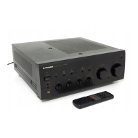
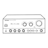
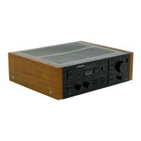
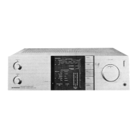
Pioneer Stereo Amplifier A-705R
Function Description:
The A-705R is a stereo amplifier designed to amplify audio signals. It is available in different models (SD, HY/EW, HY/GR) with varying power requirements. The amplifier serves as the central component for connecting various audio sources and driving loudspeakers.
Important Technical Specifications:
- Power Requirement:
- SD Model: AC110V/120 - 127V/220V/240V (with voltage selector)
- HY/EW Model: AC220 - 230V (AC240V, *)
- HY/GR Model: AC220 - 230V (AC240V, *)
- *Note: After wiring of the power-supply block at the primary winding of Power-transformer referring to the "Line Voltage Selection" described in Service Manual.
Usage Features:
The manual refers to service manual ARP2890 for A-604R/HE, indicating a potential overlap in service procedures or a related product line. The voltage selector on the SD model allows for adaptation to different regional power supplies.
Maintenance Features:
The manual provides detailed breakdowns of various assemblies within the amplifier, including:
- Input Assy: Lists components for models AWZ8359 and AWZ8306.
- MPU Assy: Lists components for models AWZ8360 and AWZ7758.
- Volume Assy: Lists components for models AWZ8363 and AWZ7724.
- Power Amp Assy: Lists components for models AWZ8350 and AWZ7706.
- Voltage Amp Assy: Lists components for models AWZ8351 and AWZ4895.
- Rec Out Assy: Discusses differences between AWZ8352 and AWZ7842.
- Diode Assy: Discusses differences between AWZ8353 and AWZ7763.
- Power Trans Assy: Discusses differences between AWZ8354 and AWZ7759.
- Power SW Assy: Lists components for models AWZ8355, AWZ8365, and AWZ7707, and includes a schematic diagram for the power switch assembly.
- Headphone Assy: Discusses differences between AWZ8357 and AWZ4885.
- Tone Assy: Lists components for models AWZ8358 and AWZ7766.
The manual also includes a "Contrast of Miscellaneous Parts" section, which highlights differences in parts between the A-705R/HY/EW, HY/GR, SD, and A-604R/HE models. This section is crucial for identifying the correct replacement parts based on the specific model. Parts marked by "NSP" are generally unavailable, and parts marked by "•" are not always kept in stock, with delivery times potentially longer.
Detailed parts lists are provided for various components, including capacitors, resistors, semiconductors, coils and filters, transformers, and switches and relays. These lists are essential for repair and maintenance, allowing technicians to identify and order specific components.
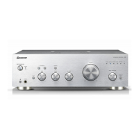
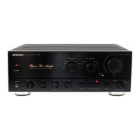
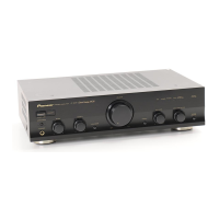
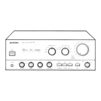
Pioneer Stereo Amplifier A-604R / A-604R-G
Function Description:
The A-604R and A-604R-G are stereo amplifiers designed for high-fidelity audio reproduction. They serve as the central hub for connecting various audio sources (CD, Tuner, Phono, Tape) and driving loudspeakers. The amplifiers offer features like loudness control, direct input, and tone adjustments to customize the sound output.
Important Technical Specifications:
Usage Features:
The manual details various front panel controls and rear panel connections:
-
Front Panel:
- Power Standby/ON switch/indicator: Controls the main power. The indicator shows power status.
- Remote control sensor window: For receiving signals from a remote control unit.
- ADPT (adaptor)/TAPE 3 button/indicator: For connecting an external adaptor or tape deck.
- Subsonic filter button/indicator: Reduces very low-frequency noise.
- Input selector switch: Selects the audio source (CD, TUNER, PHONO, LINE, TAPE 1/DAT, TAPE 2).
- Loudness button/indicator: Boosts low and high frequencies at low volume levels.
- Direct button/indicator: Bypasses tone controls for a "direct" sound.
- Treble tone control: Adjusts high frequencies.
- Bass tone control: Adjusts low frequencies.
- Volume control: Adjusts overall sound level.
- Phono selector button: Selects between MM (Moving Magnet) and MC (Moving Coil) phono cartridges.
- Speakers selector buttons: Selects speaker systems A, B, or A+B.
- Headphones jack: For private listening.
- Muting button/indicator: Temporarily mutes the sound.
- REC selector switch: Selects the source for recording.
-
Rear Panel:
- CD jacks: For connecting a CD player.
- TUNER jacks: For connecting a tuner.
- PHONO jacks: For connecting a turntable.
- GND (Turntable ground) terminal: For grounding the turntable.
- ADPT/TAPE 3 IN/PLAY jacks: For connecting an adaptor or tape deck.
- ADPT/TAPE 3 OUT/REC jacks: For connecting an adaptor or tape deck.
- SPEAKERS A terminals (Right/Left channel): For connecting main speakers.
- SPEAKERS B terminals (Right/Left channel): For connecting secondary speakers.
- LINE jacks: For connecting other line-level audio sources.
- TAPE 1/DAT PLAY jacks: For connecting a tape 1/DAT deck.
- TAPE 2 PLAY jacks: For connecting a tape 2 deck.
- TAPE 1/DAT REC jacks: For recording from a tape 1/DAT deck.
- TAPE 2 REC jacks: For recording from a tape 2 deck.
- AC OUTLETS: Switched and unswitched outlets for connecting other audio components.
- AC INLET jack: For connecting the power cord.
- CONTROL OUT jack: For controlling other Pioneer components.
- VOLTAGE SELECTORS: For adjusting the amplifier to local power supply voltage (on some models).
Maintenance Features:
The manual provides comprehensive information for maintenance and repair:
- Exploded Views, Packing and Parts List: Detailed diagrams showing the assembly of the amplifier and a list of all individual parts with their part numbers and descriptions. This is crucial for identifying and replacing components.
- PCB Parts List: Lists components for various printed circuit board assemblies, including AF Assy, Input Assy, Control Complex Assy, Voltage Amp Assy, and MPU Assy.
- Schematic and PCB Connection Diagrams: Detailed circuit diagrams and PCB layouts for various sections of the amplifier (Input Assy, Rec Out Assy, Tone Assy, Volume Assy, Headphone Assy, Voltage Amp Assy, Power Amp Assy, Power Trans Assy, Power SW Assy, Diode Assy, MPU Assy). These diagrams are essential for troubleshooting and understanding the electrical connections.
- Adjustments:
- Idle Current Adjustment: Procedure for adjusting the idle current of the power amplifier, involving connecting a DC voltmeter and adjusting VR201, VR202, VR203, and VR204. A waiting period of 5 minutes after turning on power is recommended before adjustment.
- DC Offset Adjustment: Procedure for adjusting the DC offset at the speaker terminals, involving connecting a DC voltmeter and adjusting VR201 and VR202. A waiting period of 10 minutes after turning on power is recommended before adjustment.
- Contrast of Miscellaneous Parts: Similar to the A-705R manual, this section highlights differences in parts between the A-604R/HEWZ, SD, and A-604R-G/HEZ models, aiding in correct part identification.
- Packing Assembly: Details the components included in the packing, such as the remote control unit, batteries, and operating instructions.
The manual emphasizes that parts marked by "NSP" are generally unavailable, and parts marked by "•" are not always kept in stock, which may lead to longer delivery times. It also provides contact information for Pioneer Electronic Corporation in various regions (Japan, USA, Europe, N.V., Asia Centre Pte. Ltd.).