Do you have a question about the Pioneer A-7 and is the answer not in the manual?
Details audio output power, distortion, frequency response, and sensitivity of the amplifier.
Lists power requirements, consumption, dimensions, and weight of the unit.
Explains the power switch operation and associated indicators like protection and muting.
Describes the operation of the Treble and Bass controls for adjusting the sound frequency range.
Details how to select different audio input sources using the Function Switches.
Explains the Volume Control and the Headphone Jack for listening privately.
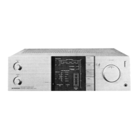
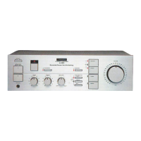
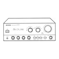
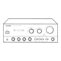
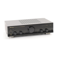
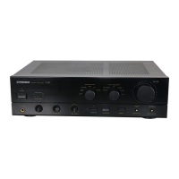
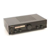
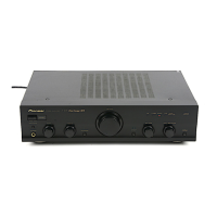
Illustrates the location of components visible on the front panel.
Shows component placement when the front panel is detached.
Diagram showing the layout of internal components when viewed from the top.
Diagram illustrating the placement of internal components from the bottom view.
Identifies components and connectors located on the rear panel.
Shows the printed circuit board layout for the Equalizer assembly.
Details the printed circuit board layout for the Power Amplifier assembly.
Illustrates the printed circuit board layout for the Switch assembly.
Displays the printed circuit board layout for the Protection assembly.
Visual representation of the unit's exterior parts and their assembly.
Procedure to adjust idle current for transistors Q1-Q4 using VR1 and VR2.
Steps to adjust VR101 and VR102 to properly light the power indicator LEDs.