EasyManua.ls Logo

Pioneer A-209 Service Manual

Pioneer A-209
34 pages
To Next Page IconTo Next Page
Page #1 background imageLoading...
Page #1 background image
ORDER NO.
PIONEER CORPORATION 4-1, Meguro 1-chome, Meguro-ku, Tokyo 153-8654, Japan
PIONEER ELECTRONICS SERVICE, INC. P.O. Box 1760, Long Beach, CA 90801-1760, U.S.A.
PIONEER EUROPE N.V. Haven 1087, Keetberglaan 1, 9120 Melsele, Belgium
PIONEER ELECTRONICS ASIACENTRE PTE. LTD. 253 Alexandra Road, #04-01, Singapore 159936
PIONEER CORPORATION 2000
c
Type
Model
Power Requirement
The voltage can be converted by
A-209R A-209 the following method.
MYXJ AC220-230V –––––
MVXJ AC220-230V –––––
MLXJ AC220-230V –––––
SBDXJ AC110V/120-127V/220V/240V With the voltage selector
RRV2283
1. SAFETY INFORMATION
......................................
2
2. EXPLODED VIEWS AND PARTS LIST
...............
3
3. BLOCK DIAGRAM AND SCHEMATIC DIAGRAM
.....
6
4. PCB CONNECTION DIAGRAM
.........................
16
5. PCB PARTS LIST
...............................................
24
6. ADJUSTMENT
....................................................
27
CONTENTS
7. GENERAL INFORMATION
................................
28
7.1 DISASSEMBLY
............................................
28
7.2 IC
..................................................................
29
8. PANEL FACILITIES AND SPECIFICATIONS
.......
30
T – ZZK APR. 2000 Printed in Japan
THIS MANUAL IS APPLICABLE TO THE FOLLOWING MODEL(S) AND TYPE(S).
PHONES
A SPEAKERS B
OFF ON
STEREO AMPLIFIER
_
—
z¿<?/B
Direct Energy MOS
TAPE 1
/CD-R/MD
TAPE 2
MONITOR
LINE
TUNER
PHONO
CD
BASS
+
TREBLE
+
VOLUME
MIN MAX
LOUDNESS DIRECT
BALANCE
R
L
INPUT SELECTOR
TAPE 2
MONITOR
POWER
Î
STEREO AMPLIFIER
A-209R
A-209

Other manuals for Pioneer A-209

Question and Answer IconNeed help?

Do you have a question about the Pioneer A-209 and is the answer not in the manual?

Pioneer A-209 Specifications

General IconGeneral
BrandPioneer
ModelA-209
CategoryAmplifier
LanguageEnglish

Summary

SAFETY INFORMATION

SAFETY PRECAUTIONS

Precautions for customer and technician safety.

PRODUCT SAFETY NOTICE

Importance of using specified replacement parts for safety.

EXPLODED VIEWS AND PARTS LIST

PACKING

Lists packing materials and components for different models.

CONTRAST TABLE

Details model-specific part differences.

EXTERIOR

EXTERIOR PARTS LIST

BLOCK DIAGRAM AND SCHEMATIC DIAGRAM

BLOCK DIAGRAM

High-level functional overview of the system's blocks.

OVERALL CONNECTION DIAGRAM

VOLUME and HEADPHONE ASSYS

AC PRIMARY ASSY

AF ASSY

FRONT L, FRONT R and OPT ASSYS

PCB CONNECTION DIAGRAM

VOLUME ASSY

PCB layout and connection points for the Volume Assy.

HEADPHONE and AC PRIMARY ASSYS

AF ASSY

FRONT L ASSY

FRONT R and OPT ASSYS

PCB PARTS LIST

VOLUME ASSY CONTRAST TABLE

Part differences for Volume Assy.

HEADPHONE ASSY OTHERS

Other components for Headphone Assy.

AC PRIMARY ASSY CONTRAST TABLE

Part differences for AC Primary Assy.

AF ASSY SEMICONDUCTORS

List of semiconductors for AF Assy.

AF ASSY CAPACITORS

List of capacitors for AF Assy.

AF ASSY RESISTORS

AF ASSY CAPACITORS

List of capacitors for AF Assy.

FRONT L ASSY SEMICONDUCTORS AND RESISTORS

FRONT R ASSY SEMICONDUCTORS AND CAPACITORS

Lists semiconductors and capacitors for Front R Assy.

ADJUSTMENT

IDLE CURRENT ADJUSTMENT

Procedure for adjusting idle current.

GENERAL INFORMATION

DISASSEMBLY

Step-by-step guide for disassembling the unit.

IC PD5443A (IC601)

PIN ASSIGNMENT

Detailed pin functions and assignments for IC601.

PANEL FACILITIES AND SPECIFICATIONS

FRONT PANEL FACILITIES

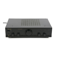
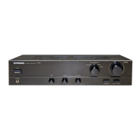
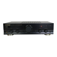
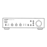
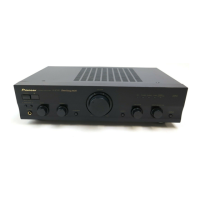
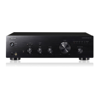
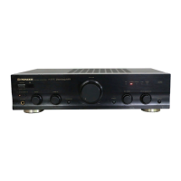
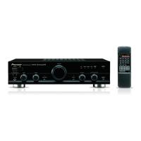
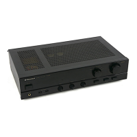
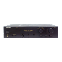
Description of controls and indicators on the front panel.

REAR PANEL

REMOTE CONTROL

SPECIFICATIONS

AMPLIFIER SECTION SPECIFICATIONS

Technical performance details of the amplifier.

POWER SUPPLY AND MISCELLANEOUS

Power requirements and physical specifications.

ACCESSORIES

List of included accessories.

Related product manuals