Do you have a question about the Pioneer AVH-3500DVD and is the answer not in the manual?
Important safety instructions for service personnel, including handling ICs and sharp edges.
Conforming to regulations, handling sharp edges, electrostatic discharge, and resetting procedures.
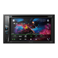
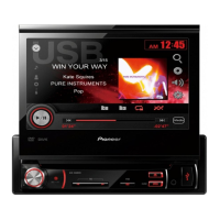
Detailed technical specifications for the unit, including general, display, DVD, audio, and tuner features.
Essential checks to ensure product quality and customer satisfaction after servicing.
Visual representation of the main unit's overall component connections and signal flow.
A step-by-step flowchart detailing the unit's power-on sequence and operational logic.
Procedure for updating the unit's firmware using a USB memory device.
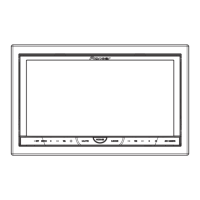
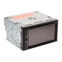
Step-by-step guide for removing the front grille assembly and the display module unit.
Procedure for calibrating the touch panel to ensure accurate input response.
Exploded view illustrating the packing configuration and components of the unit.
Exploded diagram showing external parts and their assembly (e.g., remote control, front panel).
Schematic diagram for the main PCB assembly related to tuner and RDS functions.
Diagram showing component placement and connector routing on the main PCB assembly.
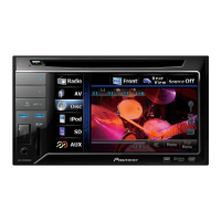
| Screen Size | 6.2 inches |
|---|---|
| DIN Size | Double DIN |
| Bluetooth | Yes |
| USB Port | Yes |
| Preamp Outputs | 3 Pairs (Front, Rear, Subwoofer) |
| Preamp Voltage | 4 volts |
| EQ Bands | 13 |
| Apple CarPlay | No |
| Android Auto | No |
| Backup Camera Input | Yes |
| AM/FM Tuner | Yes |
| iPod/iPhone Control | Yes |
| Steering Wheel Control Compatible | Yes |
| Dimensions (W x H x D) | 7 x 4 x 6.5 Inches |
| Display Type | LCD |
| Resolution | 800 x 480 |
| Video Playback | DVD, DivX, MPEG-4 |
| RMS Power Output | 14 watts |
| Peak Power Output | 50 Watts x 4 Channels |