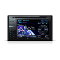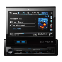
Do you have a question about the Pioneer AVH-P3250DVD/XNRD and is the answer not in the manual?
| Display Type | LCD |
|---|---|
| DVD Playback | Yes |
| CD Playback | Yes |
| MP3 Playback | Yes |
| WMA Playback | Yes |
| USB Input | Yes |
| Bluetooth | No |
| iPod Control | Yes |
| iPhone Control | Yes |
| AUX Input | Yes |
| Equalizer | 13-band |
| AM/FM Tuner | Yes |
| Video Output | Yes |
| Resolution | 800 x 480 pixels |
| Preamp Outputs | 3 (Front, Rear, Subwoofer) |
| RMS Power Output | 14 watts |
| Peak Power Output | 50W x 4 Channels |
| Power Output | 50W x 4 Channels |
Cautions regarding Class 1M laser radiation and potential exposure risks during servicing.
Manual for qualified technicians; improper repairs affect safety and warranty.
Conform to regulations, maintain safe environment, use specified parts for repairs.
Covers adjustments, lubricants, cleaning, and shipping mode requirements.
Turn off power before disassembly; handle ICs carefully due to ESD.
ESD protection for pickup unit and required skew adjustment after replacement.
Details power, dimensions, weight, screen size, pixels, color system, and temperature range.
Covers audio output power, load impedance, preout level, and equalizer settings.
Diagrams showing how to connect power, ignition, ground, lighting, speakers, and subwoofer.
Wiring for microphone, navigation unit, wired remote, and parking brake switch.
Confirms if customer complaints are solved and checks display, video, audio, and operations.
Checks DVD playback error rates, CD playback, tuner action, disc ejection, and appearance.
Shows diagrams with labels for Mother Unit, Interface PCB, DVD Core Unit, and other PCBs.
Shows the overall system architecture, including modules like DVD Mechanism, SD PCB, and BT ANT PCB.
Step-by-step chart to check the operational status starting from reset and communication.
Flowchart for inspecting pickup unit function, including LD current, RF level, and error rate checks.
Procedures to check ASMAX level and error rates using specific discs and test modes.
Flowchart for diagnosing issues related to iPod, USB, AVCC5 voltage, DACCLK, and audio circuits.
Checks the voltage at the STANBY test point relative to DGND1.
Verifies VDD5, VCC33, and VCC12 voltages at specific test points against reference DGND1.
Checks the voltage at the XRES test point relative to DGND1 to verify the reset signal.
Checks the voltage at the VSENS test point relative to DGND1, related to power supply configuration.
Checks the 27 MHz clock signal generated by the master crystal oscillator (X1501).
Verifies the communication interface between the LSI and SDRAM memory.
Verifies VD8 and VCC5 power supply voltages at specific test points relative to PGND3 and AGND1.
Checks the AVCC5 voltage at the stylus, using PGND and GNDAU as reference.
Checks the DACCLK for Audio-DAC created by IC1501 using the 27 MHz crystal oscillator.
Lists error statuses, UART codes, meanings, generation sources, and reset methods.
Demonstrates handling OK vs NG for specific parts, emphasizing proper handling.
Crucial precautions for DVD adjustment, including reference voltages, grounding, and handling measurement devices.
Details when SKEW adjustment is required, equipment needed, and connection drawing.
Two methods for SKEW adjustment: monitoring RF waves via oscilloscope or checking numerical RF level via OSD.
Cautions against touching optical parts, shaded areas, and springs on the PU.
Detailed schematic diagram of the Mother Unit, focusing on audio circuits and signal paths.


 Loading...