Do you have a question about the Pioneer AVH-P7800DVD/UC and is the answer not in the manual?
| Resolution | 800 x 480 pixels |
|---|---|
| DVD Playback | Yes |
| CD Playback | Yes |
| MP3 Playback | Yes |
| WMA Playback | Yes |
| AAC Playback | Yes |
| DivX Playback | Yes |
| USB Input | Yes |
| Bluetooth | No |
| iPod Compatibility | Yes |
| iPhone Control | Yes |
| Preamp Outputs | 3 pairs (front, rear, subwoofer) |
| Peak Power Output | 50 Watts x 4 Channels |
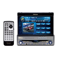
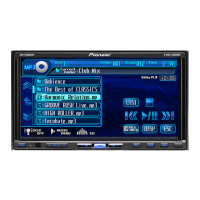
| Touchscreen | Yes |
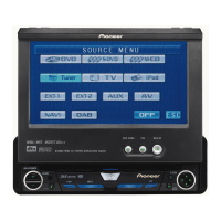
| Motorized Display | Yes |
| Remote Control | Yes |
| Rear View Camera Input | Yes |
| Video Output | Yes |
| Equalizer | 13-band graphic equalizer |
General safety guidelines for service personnel.
Precautions for handling components and unit during service.
Electrical and physical characteristics of the unit.
Audio output and frequency response parameters.
Tuning range, sensitivity, and distortion characteristics.
Disc compatibility and playback features.
List of items included in the product packaging.
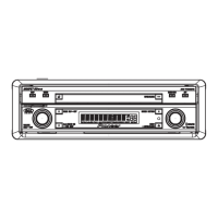
Exploded view of the unit's exterior components.
Exploded view of the unit's exterior components (continued).
Exploded view of the unit's exterior components (continued).
Exploded view and parts list for the tuner selector assembly.
Exploded view and parts list for accessories and power supply.
Exploded view and parts list for the DVD mechanism module.
Diagram showing how different units are interconnected.
Functional block diagram of the unit's internal circuitry.
PCB layout and component placement for the DVD mother unit.
PCB layout and component placement for the keyboard unit.
PCB layout and component placement for the DVD core unit.
PCB layouts for compound units A and B.
PCB layout and component placement for the monitor keyboard unit.
PCB layout and component placement for the monitor unit.
PCB layout and component placement for the power supply unit.
PCB layout and component placement for the tuner selector unit.
PCB layout and component placement for the amplifier unit.
PCB layouts for main, switch, and volume boards.
List of integrated circuits used in the unit with part numbers.
List of transistors used in the unit with part numbers.
Required jigs and their connections for adjustment procedures.
Procedures for adjusting the DVD mechanism and its optical performance.
Procedures for adjusting the video signal levels.
Procedures for adjusting monitor display parameters.
Procedures for adjusting DC-DC converter outputs and frequency.
Procedure for checking the PCL output from the system microcomputer.
Procedures and settings for the monitor test mode.
Procedures for calibrating and verifying the touch panel operation.
Expected waveforms for FE (Focus Error) test mode.
Expected waveforms for Focus Close adjustment.
List of errors related to disc media and their meanings.
List of focus error codes and their descriptions.
Error codes related to command requests and their meanings.
Specific adjustment failures and their error codes.
General diagnostic information for troubleshooting.
Step-by-step procedures for disassembling the unit.
Diagrams showing the location of various PCBs within the unit.
Description of the function of each connector on the unit.
List of integrated circuits used in the unit with part numbers.
List of display components and their part numbers.
Overview of the unit's operational flow.
Description of the buttons and functions on the main unit.
Explanation of remote control button functions in AVH and DVD modes.
Diagram illustrating how the unit connects to accessories and power sources.
List of extension cords used for testing and connection.
List of relay PCBs used for testing.
List of greases and their applications for lubrication.