EasyManua.ls Logo

Pioneer CLD-D925 Service Manual

Pioneer CLD-D925
79 pages
To Next Page IconTo Next Page
Page #1 background imageLoading...
Page #1 background image
W)
PIONEER’
The
Art
of
Entertainment
Service
ORDER
NO.
RRV1546
CD
CDV
LD
PLAYER
CLD-D925
THIS
MANUAL
IS
APPLICABLE
TO
THE
FOLLOWING
MODEL(S)
AND
TYPE(S).
CONTENTS
1.
SAFETY
INFORMATION
POVECTeTEeTEeTeereT
Ter
Teer
eT
Teer
2
7.
AGEING
MODE
Poem
ccc
cccerwcerecesesoccccececssnseses
64
2.
PACKING,
EXPLODED
VIEWS
8.
DISASSEMBLY/ASSEMBLY
«-+-+++++++-+++-+++++-
65
AND
PARTS
LIST
Po
eeeececcccccvccece
3
9.
IC
INFORMATION
Come
eee
ec
cane
reece
cnvecececeseseee
68
3.
SCHEMATIC
AND
10.
BLOCK
DIAGRAMS
-++++++-++0+00sseseeestsesesesene
93
PCB
CONNECTION
DIAGRAMS
---eesseeeeeeeees
13
11.
FL
INFORMATION:
+-:-++:-ececececececeeertencneeees
97
4.
PCB
PARTS
LIST
Seen
cee
eeecee
eee
eeecccsececcccveeseeses
37
12.
PANEL
FACILITIES
oe
ccc
cece
cece
receerencrcccenscece
98
5.
ADJUSTMENTS
«svcerrceccecncecsectcesevessesceseesees
42
13.
SPECIFICATIONS
-:----scesseeceeceececeeceeceereees
99
6.
SELF-
DIAGNOSTIC
FUNCTIONS
-+++++++++++++++
62
PIONEER
ELECTRONIC
CORPORATION
4-1,
Meguro
1-Chome,
Meguro-ku,
Tokyo
153,
Japan
PIONEER
ELECTRONICS
SERVICE,
INC.
P.O.
Box
1760,
Long
Beach,
CA
90801-1760,
U.S.A.
PIONEER
ELECTRONIC
(EUROPE)
N.V.
Haven
1087,
Keetberglaan
1,
9120
Melsele,
Belgium
PIONEER
ELECTRONICS
ASIACENTRE
PTE.
LTD.
501
Orchard
Road,
#10-00
Lane
Crawford
Place,
Singapore
0923
©
PIONEER
ELECTRONIC
CORPORATION
1996
Foes
APRESS
nda
Question and Answer IconNeed help?

Do you have a question about the Pioneer CLD-D925 and is the answer not in the manual?

Pioneer CLD-D925 Specifications

Power IconPower
power requirementsAC 220 ~ 240 V, 50/60 Hz
power consumption51 W
Operating Environment IconOperating Environment
operating temperature+5°C ~ +35°C
operating humidity5% ~ 85%
Audio Characteristics IconAudio Characteristics
frequency response4 Hz - 20 kHz
signal-to-noise ratio115 dB (EIAJ)
dynamic range97 dB (EIAJ)
total harmonic distortion0.003 % (EIAJ)
Video Characteristics IconVideo Characteristics
video output level1 Vp-p nominal
s-video output luminance level1 Vp-p (75)
s-video output chrominance level286 mVp-p (75Q)
Weight and Dimensions IconWeight and Dimensions
weight6.8 kg
width420 mm
depth407 mm
height132 mm

Summary

1. Safety Information

Laser Warning Labels

Details on laser warning labels and signs for safety.

Additional Laser Safety Precautions

Further safety guidelines regarding laser diode exposure.

2. Packing, Exploded Views, and Parts Lists

Packing and Model Contrast

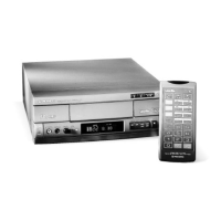
Information on packing and differences between CLD-D925/WY and WV models.

Exploded Views and Parts List for CLD-D925/WY

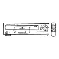
Detailed exploded diagrams and parts for the CLD-D925/WY model.

2.2 Exterior and Disc Tray Section

Model Contrast

Highlights differences in exterior and disc tray between CLD-D925/WY and WV.

Parts List for Exterior and Disc Tray

Component list for exterior parts and the disc tray section.

2.3 Top View Section

Top View Parts List

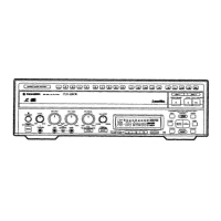
Component list for the top view section of the player.

2.4 Front Panel Section

Front Panel Parts List

Component list for the front panel of the player.

2.5 Bottom View Section

Bottom View Parts List

Component list for the bottom view section of the player.

2.6 Servo Mechanism Section

Servo Mechanism Parts List

Component list for the servo mechanism section.

2.7 Loading Mechanism Section

Loading Mechanism Parts List

Component list for the loading mechanism section.

2.8 Carriage Assembly

Carriage Assembly Parts List

Component list for the carriage assembly.

3. Schematic and PCB Connection Diagrams

Schematic Diagram Notes

Important notes regarding schematic diagrams and component details.

PCB Diagram Notes

Important notes regarding PCB connection diagrams and component symbols.

Waveforms and Voltage - Main Assy (1/2)

Main Assy Waveforms (Part 1)

Waveform and voltage measurements for the Main Assy, part 1.

IC901 Block Diagram

Internal block diagram of IC901, illustrating its functionality.

Main Assy Waveforms and Voltages (Part 2)

Main Assy Waveforms (Part 2)

Waveform and voltage measurements for the Main Assy, part 2.

DMYC Assy Waveforms and Voltages

DMYC Assy Waveforms

Waveform and voltage measurements for the DMYC Assy.

Various IC Waveforms and Voltages

Specific IC Waveforms and Voltages

Waveform and voltage data for multiple ICs (IC701, IC702, etc.).

4. PCB Parts List

Assembly List Overview

General list of assemblies and their related parts.

Specific Assembly Component Lists

Detailed component lists for various major assemblies (BISB, PWSB, etc.).

5. Adjustments

Mechanical Adjustments

Procedures for mechanical adjustments on the player.

Main Assy Electrical Adjustments

Electrical adjustment procedures for the Main Assy.

DMYC Assy Electrical Adjustments

Electrical adjustment procedures for the DMYC Assy.

5.2 Jigs and Measuring Instruments

Required Jigs and Instruments

List of essential tools and equipment for performing adjustments.

5.3 Test Mode

Entering and Setting Test Mode

Procedure for turning on test mode and setting the disc.

5.3 Test Mode

Test Mode Play and Off Operations

Steps for operating the player in PLAY and OFF test modes.

5.4 EEPROM Initialization Method

EEPROM Initialization Procedure

Steps to initialize the EEPROM settings.

5.5 Necessary Adjustment Points

Adjustments for Mechanism Assy Exchange

Adjustment points required after exchanging mechanism assembly parts.

Adjustments for PCB Assy Exchange

Adjustment points required after exchanging PCB assemblies (MAIN/DMYC).

5.6 Mechanical Adjustment

Tilt Offset Adjustment

Procedure to adjust the tilt offset on the player.

Tangential Direction Angle Adjustment (Side A)

Adjusting the tangential direction angle for Side A.

5.6 Mechanical Adjustment

Spindle Motor Centering Adjustment (Side A)

Procedure to center the spindle motor for Side A.

Crosstalk Check and Fine Tilt Offset (Side A)

Checking crosstalk and fine-tuning tilt offset for Side A.

5.6 Mechanical Adjustment

Focus Servo Loop Gain Adjustment

Adjusting the gain for the focus servo loop.

Tracking Servo Loop Gain Adjustment

Adjusting the gain for the tracking servo loop.

5.6 Mechanical Adjustment

Tangential Direction Angle Adjustment (Side B)

Adjusting the tangential direction angle for Side B.

Spindle Motor Centering Adjustment (Side B)

Procedure to center the spindle motor for Side B.

5.6 Mechanical Adjustment

Crosstalk Check and Fine Tilt Offset (Side B)

Checking crosstalk and fine-tuning tilt offset for Side B.

5.7 Electrical Adjustment of Main Assy

NTSC Master Clock Adjustment

Adjusting the NTSC master clock frequency.

5.7 Electrical Adjustment of Main Assy

PAL Master Clock Adjustment

Adjusting the PAL master clock frequency.

Output Video Level Adjustment

Adjusting the output video signal level.

5.7 Electrical Adjustment of Main Assy

PLL Offset Adjustment

Adjusting the PLL offset for stable operation.

5.8 Electrical Adjustment of DMYC Assy

17MHz Free-run Frequency Adjustment

Adjusting the 17MHz free-run frequency.

4.43MHz Free-run Frequency Adjustment for Y/C Separation

Adjusting 4.43MHz frequency for Y/C separation.

5.8 Electrical Adjustment of DMYC Assy

PAL 4.43MHz Free-run Frequency Adjustment for RGB Decoder

Adjusting PAL 4.43MHz frequency for RGB decoder.

NTSC 3.58MHz Free-run Frequency Adjustment for RGB Decoder

Adjusting NTSC 3.58MHz frequency for RGB decoder.

5.8 Electrical Adjustment of DMYC Assy

NTSC Y Level Adjustment

Adjusting the NTSC Y signal level.

RGB Decoder Y Level Adjustment

Adjusting the Y level for the RGB decoder.

5.8 Electrical Adjustment of DMYC Assy

RGB Decoder HUE Adjustment

Adjusting the HUE for the RGB decoder.

RGB Decoder NTSC Chroma Level Adjustment

Adjusting NTSC chroma level for RGB decoder.

5.8 Electrical Adjustment of DMYC Assy

PAL Y Level Adjustment

Adjusting the PAL Y signal level.

Coarse RGB Decoder PAL Chroma Level Adjustment

Coarsely adjusting PAL chroma level for RGB decoder.

5.8 Electrical Adjustment of DMYC Assy

RGB Decoder PAL Delay Line Amp. Gain Adjustment

Adjusting gain for PAL delay line amp in RGB decoder.

RGB Decoder PAL DAT Adjustment

Performing PAL DAT adjustment for the RGB decoder.

5.8 Electrical Adjustment of DMYC Assy

Fine RGB Decoder PAL Chroma Level Adjustment

Finely adjusting PAL chroma level for RGB decoder.

5.9 Operations in the Test Mode

Test Mode Remote Control Unit Operations

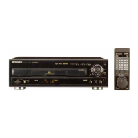
Instructions for using the GGF1067 remote control unit in test mode.

TV Monitor Display in Test Mode

Interpreting the TV monitor display during test mode operations.

6. Self-Diagnostic Functions

Overview of Self-Diagnostic Functions

Description of automatic error code display and retrieval.

6.2 Mechanism Switch Information

Mechanism Switch Data Format

Format of mechanism switch information transmitted to mode control.

7. Ageing Mode

Ageing Mode: ON

Procedure for enabling and operating the ageing mode.

Ageing Mode: OFF

Procedure for disabling and exiting the ageing mode.

8. Disassembly/Assembly

Disc Tray Disassembly and Assembly

Step-by-step instructions for disassembling and assembling the disc tray.

Main Assy Disassembly and Assembly

Step-by-step instructions for disassembling and assembling the main assembly.

8.3 Flexible Cable Installation for Carriage Assy

Flexible Cable Installation Procedure

Instructions for installing the flexible cable for the carriage assembly.

9. IC Information

FLKY Assy IC Information

Information on ICs (IC101, IC102) on the FLKY assembly.

Main Assy IC Information (Part 1)

Information on Main Assy ICs (IC101, IC201, IC351, IC400, IC500, IC801).

DMYC Assy IC Information (Part 1)

Information on DMYC Assy ICs (IC101, IC102, IC201).

DMYC Assy IC Information (Part 2)

Information on DMYC Assy ICs (IC211, IC401).

10. Block Diagrams

10.1 Overall Block Diagram

A comprehensive block diagram of the player's system.

10.2 DMYC Block Diagram

DMYC Block Diagram Details

Detailed block diagram for the DMYC section of the player.

12. Panel Facilities

Front Panel Controls and Indicators

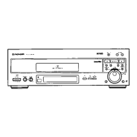
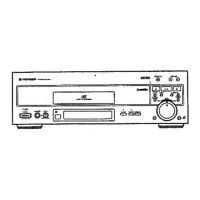
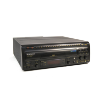
Description of the front panel buttons, switches, and indicators.

Display Window Indicators

Explanation of the symbols and indicators shown in the display window.

13. Specifications

General Specifications

Overall system specifications including laser and power requirements.

Video Characteristics

Specifications related to the video output format and levels.

Audio Characteristics

Specifications for audio output levels and digital audio performance.

Other Terminals and Accessories

Details on external terminals and included accessories.

Related product manuals