Do you have a question about the Pioneer CT-70R and is the answer not in the manual?
General safety checks and leakage current measurement.
Highlights special safety characteristics of replacement parts.
Details performance metrics like frequency response, wow/flutter, S/N.
Covers power, dimensions, weight, and included accessories.
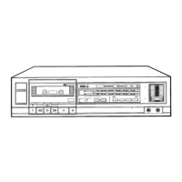
Power, Timer, Eject, Direction, Counter, Reset controls.
Memory, Play, Rew, FF, Stop, Pause, Record, Mute controls.
Dolby NR, Music Search/Skip, Music Repeat, Blank Search functions.
Dolby B/C, Tape Indicators, Mode, MPX Filter selections.
Bonnet case, front panel, and bottom plate removal steps.
Tape transport, head assembly, and capstan belt removal.
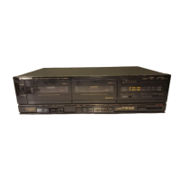
Locates parts on the front panel view.
Locates internal parts from the top view.
Diagram showing connections between different circuit boards.
Provides the complete electronic schematic for the unit.
Lists miscellaneous, fuses, capacitors, resistors, semiconductors.
Lists parts for specific assemblies like Dolby NR, Control.
Covers pinch roller, head azimuth, tape transport, speed, torque, and door.
Covers Head Azimuth, Tape Transport, Playback EQ, and Playback Level.
Details the erase current adjustment procedure.
Covers Recording Level, Meter OdB Check, Leader Tape Detector.
Lists parts differing from KU type for HE, HB, HP models.
Lists parts differing from KU type for KC model.
Lists parts differing from KU type for D/D/G models.
| Track System | 4-track, 2-channel stereo |
|---|---|
| Tape Speed | 4.8 cm/s |
| Heads | 1 x record, 1 x playback, 1 x erase |
| Total Harmonic Distortion | 0.8% |
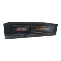
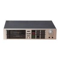
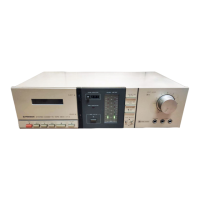
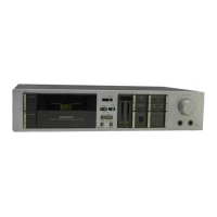
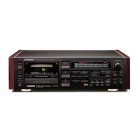
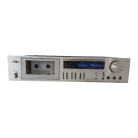
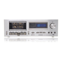
| Type | Stereo Cassette Deck |
| Tape Type | Type I, Type II, Type IV |
| Noise Reduction | B, C |
| Frequency Response | 20Hz - 20kHz (Metal tape) |
| Dimensions | 420 x 120 x 300mm |