EasyManua.ls Logo

Pioneer CT-3 User Manual

Pioneer CT-3
52 pages
To Next Page IconTo Next Page
Page #1 background imageLoading...
Page #1 background image
()
rrloNEErl'
ORDER NO.
ARP-061-O
STEREO CASSETTE TAPE DECK
GT-3
MODEL
CT.3
COMES IN
SIX VERSIONS
DISTINGUISHED
AS FOLLOWS:
r
This
service manual
is
applicable
to
the
KU
type.
When
repairing
the KC
and D
types,
please
see
page
23.
r
when
repairing
the HE,
HB
and HP types,
please
see the
additional
service manual
<ARp-060>.
r
Ce
manuel
d'instruction
se refdre
au
mode
de r6glage,
en frangais.
.
Este manual
de servicio
trata
del m6todo
de
ajuste escrit
en
espafiol.
CONTENTS
4
6
I
14
14
18
21
23
o
1. SPEC|F|CAT|ONS
.....
2.
FRONT PANEL
FACILITIES
3. DISASSEMBLY
4. PARTS
LOCATION
5. EXPLODED
VIEWS
AND PARTS
LIST
. .
6.
PAC
KING
7. PARTS
LIST
. , .
8.
P.C.
BOARD CONNECTION
DIAGRAM
9.
SCHEMATIC DIAGRAIV
10. FOR
KC AND D
TYPES
11. MECHANICAL
ADJUSTIVENTS
. . .
REclncesu€cnNtouEs..
. . . .
AJUSTESMECANTCOS
.. .. ....
12. ELECTRICAL
ADJUSTMENTS
. . ,
REGLAGES
ELECTRIOUES
.
...
AJUSTES
E LE LECTRIO
I3.
BLOCK DIAGRAM
,I4.
CIRCUIT
DESCRIPTIONS
. . .
15. CASSETTE
DECK MECHANICAL
24
27
31
J5
39
40
44
OPERATIONS
(SIMPIFIED
DESCRIPTIONI
PIGINEEFI ELECTFIE'NIC
CCtFlttOFlATlClN
z1
I
Mesu.o 1
chome. Mesu.o k! rokyo
1s3. J6p6n
u,€t. FICfNEEFI
ELECTFICINIC€|
CC'FIFC'FAIICIN
85 O:fo.d D.rve, Moonacr'e, New
Je.sey A7A24, uS
A.
F lctNEEFr
ELECTFIC|N|C
(EUFG|9E
N.V. Lu thaae. Hawerr
9. 2O3O
An.we.p,
Bergtrrm
PI()NEEFI
ELECTFIONIC€
AU€IIFIALIA FlY.
LYEI.
174 rA4
Bou.da.y Road.
B.aesde. V'crora
3135. Ausr.6 6
yG
..jOCT.
t98l
Type
Voltage
Rem€rks
KU
ACl2OV
only
U.S.A. model
KC
ACl20V
only
Canada
model
D AC12OV,22OV
and 240V
{switchablel
General
expor't model
AC22OV
and 24OV
(switchable)
Europe model
HB
AC22OV
and 24OV
(switchable)
United Kingdom model
HP
AC22OV
and
24OV
(switchable)
Australia
model
Prinred in
lap,
n
Question and Answer IconNeed help?

Do you have a question about the Pioneer CT-3 and is the answer not in the manual?

Pioneer CT-3 Specifications

General IconGeneral
BrandPioneer
ModelCT-3
CategoryTape Deck
LanguageEnglish

Summary

Product Specifications

Specifications Overview

Details technical specifications, dimensions, power requirements, and included accessories for the CT-3.

Front Panel Facilities

Front Panel Controls Overview

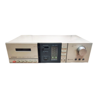
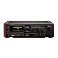
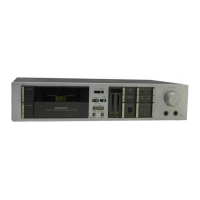
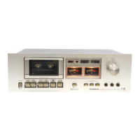
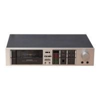
Identifies and describes the function of each control and indicator on the front panel.

Initial Disassembly Steps

Front Component Removal

Details initial steps for disassembling the cassette deck, focusing on front and accessible components.

Internal Disassembly Steps

Internal Assembly Removal

Details removal of internal assemblies like switch, mechanism, meter, and indicator.

Parts Location - Front Views

Front Panel Component Identification

Illustrates the location of parts on the cassette deck's front panel.

Parts Location - Top and Rear Views

Top and Rear Panel Component Identification

Illustrates the location of parts in top (with bonnet removed) and rear panel views.

Exploded Views and Parts List Introduction

Exploded Diagrams Overview

Visual representation of internal components and their assembly order.

Detailed Parts List

Component Part Numbers and Descriptions

Comprehensive list of all parts with part numbers and descriptions for ordering.

Packing and Parts Ordering Information

Packing Instructions

Instructions and diagrams for packing the unit for shipping or storage.

Parts Ordering Notes

Notes on converting resistance values and ordering replacement parts.

Printed Circuit Board Assemblies

Component Lists (Capacitors, Semiconductors, Resistors)

Details various P.C. board assemblies, including capacitors, semiconductors, and resistors.

Component Lists and Diagrams

Semiconductors, Switches, and Coils

Lists semiconductors, switches, coils, and other miscellaneous components with their part numbers.

Transistor and IC Identification

External Appearance and Pin Diagrams

Illustrates the external appearance and pin configurations of various transistors and ICs.

P.C. Board Connection Diagrams

Indicator, Switch, and Volume Assemblies

Shows electrical connections for indicator, switch, and volume assemblies.

P.C. Board Wiring Details

Mother and Meter Assemblies Wiring

Illustrates electrical wiring for mother and meter assemblies.

Schematic Diagram - KU and KC Types

Main Circuit Schematic

Detailed schematic diagram for KU and KC type models, illustrating circuit functionality.

Schematic Diagram Analysis

Circuit Operation Descriptions

Explanation of signal paths, muting, and Music Search (MS) operations.

Model Specific Information - KC and D Types

Miscellaneous Parts Contrast

Highlights differences in miscellaneous parts for KC and D type models compared to KU.

D Type Schematic and Specifications

Provides schematic and specifications specific to the D type model.

Mechanical Adjustment Procedures - Part 1

Pinch Roller and Reel Base Torque

Adjusting pinch roller pressure and reel base torque.

Mechanical Adjustment Procedures - Part 2

Tape Speed and REC Switch Calibration

Calibrating tape speed and the REC switch mechanism.

Block Diagram Overview

Overall System Block Diagram

High-level overview of the CT-3's internal circuitry and signal flow.

Circuit Descriptions - Signal Paths

Playback Signal Path

Describes the audio signal path from the playback head to the output.

Recording Signal Path

Describes the signal path for recording audio from inputs to the recording head.

Circuit Descriptions - Muting and Control

Muting Circuit Operation

Explains the function of the muting circuit to prevent transient noise.

Power Switch and Mode Muting

Details muting operations related to power switching and mode changes.

Circuit Descriptions - Special Functions

Music Search (MS) Operation

Explains the operation of the Music Search (MS) function.

Blank Detector (BA336) Function

Describes the function of the BA336 IC for tape blank detection.

Circuit Descriptions - Timing Analysis

BA336 Timing Chart and Operation

Timing chart and operational details of the BA336 blank detector IC.

Cassette Deck Mechanical Operations - Stop Mode

Stop Mode Description

Describes the mechanical state of the deck in STOP mode.

Cassette Deck Mechanical Operations - Play Mode

Play Mode Operation

Details the mechanical sequence for engaging the PLAY mode.

Cassette Deck Mechanical Operations - Transitions

Play to Stop Transition

Describes the mechanical sequence for transitioning from PLAY to STOP mode.

Play Pause and Pause Release

Explains the mechanical operations for PAUSE and PAUSE RELEASE.

Cassette Deck Mechanical Operations - Record Mode

Record Mode Operations

Details the mechanical sequence for engaging the REC mode.

Cassette Deck Mechanical Operations - Rec to Stop

Record to Stop Transition

Describes the mechanical sequence for transitioning from REC to STOP mode.

Cassette Deck Mechanical Operations - FF/REW

Fast Forward and Rewind Operations

Details the mechanical sequences for FF and REW operations.

Cassette Deck Mechanical Operations - Special Modes

Music Search (MS) Operations

Describes the mechanical operations for the Music Search (MS) function.

Auto-Stop Operations

Explains the mechanical sequence for the auto-stop function.

Cassette Deck Mechanical Operations - Timing Charts

Timing Charts - PLAY Operations

Timing chart illustrating the sequence of operations during PLAY mode.

Cassette Deck Mechanical Operations - Timing Analysis

Timing Charts - REC and FAST Operations

Timing charts illustrating sequences for REC and FAST operations.

Related product manuals