Do you have a question about the Pioneer CT-9R and is the answer not in the manual?
Important notes and listing of miscellaneous parts.
Lists parts for various PC board assemblies.
PCB layouts for Mic, Sub, and Headphone amplifiers.
PCB layouts for Mother, Power Supply, and Connector assemblies.
PCB layouts for Equalizer, Function Switch, and other assemblies.
Circuit diagrams for signal processing and audio paths.
Circuit diagrams for the power supply unit.
Procedures for pinch roller pressure, head azimuth, and tape path alignment.
Adjusting motor speeds, tape torque, and reel base tension.
Adjusting head azimuth, equalizer, and playback levels.
Setting recording levels, bias, and frequency response.
Adjusting BLE and leader tape detection functions.
| Track System | 4-track, 2-channel stereo |
|---|---|
| Tape Speed | 4.76 cm/s |
| Tape Type | type I, CrO2, Metal |
| Total Harmonic Distortion | 0.8% |
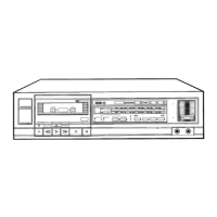
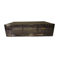
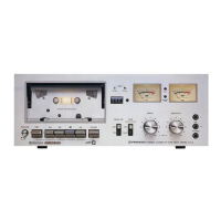
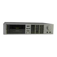
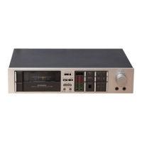
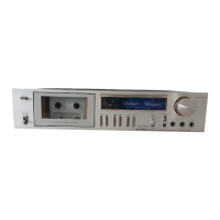
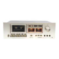
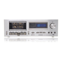
| Type | Cassette Deck |
| Heads | 3 |
| Motor | DC servo motor |
| Noise Reduction | Dolby B, Dolby C |
| Frequency Response | 20Hz to 20kHz (Metal tape) |
| Dimensions | 420 x 115 x 335 mm |