EasyManua.ls Logo

Pioneer CT-F500 Service Manual

Pioneer CT-F500
47 pages
To Next Page IconTo Next Page
Page #1 background imageLoading...
Page #1 background image

Table of Contents

Other manuals for Pioneer CT-F500

Question and Answer IconNeed help?

Do you have a question about the Pioneer CT-F500 and is the answer not in the manual?

Pioneer CT-F500 Specifications

General IconGeneral
BrandPioneer
ModelCT-F500
CategoryTape Deck
LanguageEnglish

Summary

1. SPECIFICATIONS

2. FRONT PANEL FACILITIES

POWER SWITCH

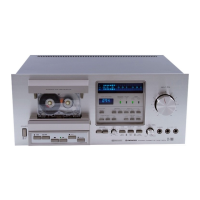
Controls the unit's power supply and turns on level meters.

INPUT LEVEL CONTROLS

Adjusts input signal levels from MIC and line inputs.

DOLBY NR SWITCH

Activates the Dolby noise reduction system.

PRECAUTIONS

HANDLING THE POWER CORD

Safety instructions for power cord usage.

PRECAUTIONS FOR USE

General safety and handling warnings for the unit.

KEEP THE HEAD SECTION CLEAN

Importance of cleaning heads, capstan, and pinch roller.

3. DISASSEMBLY

3.1 FRONT PANEL, PANEL-STAY AND MECHANISM

Steps for removing the front panel, stay, and mechanism.

7. CIRCUIT DESCRIPTIONS

7.1 RECORDING AND PLAYBACK CIRCUIT

Explanation of signal paths for recording and playback.

7.5 POWER SUPPLY CIRCUIT

Explains the power supply circuit.

8. MECHANICAL DESCRIPTIONS

8.1 PLAY OPERATION

Describes the mechanical steps during playback.

8.2 AUTO-STOP OPERATION

Explains the mechanism for automatic tape stopping.

8.3 FF, REW

Details the mechanical operation for fast forward and rewind.

9. MECHANICAL ADJUSTMENTS

9.1 TAPE SPEED ADJUSTMENT

Procedure to adjust tape playback speed.

9.4 PINCH ROLLER PRESSURE ADJUSTMENT

Sets the correct pressure for the pinch roller.

10. ELECTRICAL ADJUSTMENTS

10.1 HEAD AZIMUTH ADJUSTMENT

Adjusts head alignment for optimal stereo imaging.

10.3 PLAYBACK LEVEL ADJUSTMENT

Sets playback level, critical for Dolby calibration.

10.7 RECORD AND PLAYBACK FREQUENCY ADJUSTMENT

Adjusts frequency response for recording and playback.

10.8 RECORDING LEVEL ADJUSTMENT

Sets the recording level for optimal performance.

10.9 DOLBY CIRCUIT ADJUSTMENT

Calibrates the Dolby noise reduction circuit.

11. SCHEMATIC DIAGRAMS, P.C. BOARD PATTERNS AND PARTS LIST

11.2 CONNECTION DIAGRAM

Shows how components and assemblies are connected.

11.3 SCHEMATIC DIAGRAM

Detailed electrical circuit diagrams.

Related product manuals