Do you have a question about the Pioneer CT-F1000 and is the answer not in the manual?
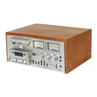
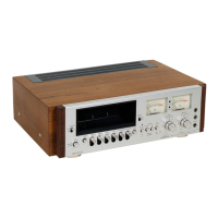
Shows the location of controls and indicators on the front panel.
Identifies components visible from the front with the panel detached.
Shows internal component layout from the top, with the cover removed.
Details the rear panel connections and ports.
Lists various switches, transformers, capacitors, resistors, assemblies, and others.
Visual identification of common semiconductors used in the unit.
Shows the internal circuit of specific integrated circuits.
Illustrates how to connect the unit to other audio equipment.
Detailed electronic schematic of the entire unit's circuitry.
Schematic and layout for the main printed circuit board.
Schematic for the volume control circuit.
Schematic for the unit's power supply section.
Schematic for the recording equalization circuitry.
Schematic for the playback equalization circuitry.
Schematic for the Dolby noise reduction circuitry.
Schematic for the VU meter and associated circuitry.
Schematic for the integrated amplifier IC assembly.
Schematic for the peak level indicator amplifier.
Schematic for the pause switch mechanism.
Schematic for the built-in test tone oscillator.
Schematic for the flat amplifier stage.
Schematic for the front panel indicator LEDs and circuits.
Diagram showing fuse locations and ratings.
| Type | 3-head, single compact cassette deck |
|---|---|
| Track System | 4-track, 2-channel stereo |
| Tape Speed | 4.76 cm/s |
| Motor | DC servo motor |
| Total Harmonic Distortion | 0.8% |
| Output | 0.45V (line) |
| Heads | 1 x record, 1 x playback, 1 x erase |
| Frequency Response | 20Hz to 20kHz |
| Dimensions | 420 x 187 x 375mm |
| Tape Type | Metal |