EasyManua.ls Logo

Pioneer CT-1040W Service Manual

Pioneer CT-1040W
42 pages
To Next Page IconTo Next Page
Page #1 background imageLoading...
Page #1 background image
d)
PIONEER’
PSY
st
44
ee
PAZ
ETIEY
REPAIR
&
ADJUSTMENTS
|
a
2
=
;
ORDER
NO.
ARP-
266-0
STEREO
DOUBLE
CASSETTE
TAPE
DECK
CT-ioqow
MODEL
CT-1040W
COMES
IN
SIX
VERSIONS
DISTINGUISHED
AS
FOLLOWS:
Voltage
Remarks
AC120V
only
U.S.A.
model
AC220V,
240V
(switchable)
European
continent
model
AC220V,
240V
(switchable)
United
Kingdom
model
AC220V,
240V
(switchable)
Australia
model
AC120V,
220V,
240V
(switchable)
General
export
model
AC120V,
220V,
240V
(switchable)
U.S.
Military
model
e
This
service
manual
is
applicable
to
the
CT-1040W/KU.
For
servicing
of
the
other
types,
please
refer
to
page
56.
e
For
the
circuit
and
mechanism
descriptions,
please
refer
to
the
CT-1040W,
CT-X8W
service
manual
(ARP-370).
e@
Ce
manuel
d’instruction
se
refére
au
mode
de
réglage,
en
francais.
Este
manuel
de
servicio
trata
del
método
de
ajuste
escrito
en
espafol.
CONTENTS
1.
SPECIFICATIONS
.............00
0000s
2
9.
ELECTRICALPARTS
LIST
...........---
31
2.
FRONT
PANEL
FACILITIES..............
3
10.
ADJUSTMENTS
.........2
020s
cree
ete
35
3.
DISASSEMBLY
.............
00000
eee
6
REGLAGE
4
ke
icc
es
ee
oe
ee
Pa
42
4.
PARTSLOCATION
.........
00002
e
eee
8
PMUS
TBs
des
fSedis
oars
haiti
owe
Reet
ae
49
5.
EXPLODED
VIEW
AND
PARTS
LIST........
10
11.
SAFETY
INFORMATION
....----
+0022
205
55
62.
PACKING
seis
ba
Sein
tae
ha
Wide
Be
SEE
20
12.
SUPPLEMENT
FOR
HE,
HB
AND
HP
TYPES
-
..
56
7.
P.C.
BOARD
CONNECTION
DIAGRAM
......
21
13.
SUPPLEMENT
FORD
ANDD/GTYPES...---
59
8.
SCHEMATIC
DIAGRAM......
lg
Ae
etnateardess
27
PIONEER
ELECTRONIC
CORPORATION
2-1.
Meguro
1-Chome,
Meguro-ku,
Tokyo
153,
Japan
PIONEER
ELECTRONICS
(USA)
INC.
1925
£.
Dominguez
St.,
Long
Beach,
California
30810
USA.
PIONEER
ELECTRONIC
[EUROPE]
N.V.
Keetbergiaan
1,
2740
Beveren,
Belgium
PIONEER
ELECTRONICS
AUSTRALIA
PTY.
LTD.
178-184
Boundary
Road,
Braeside,
Victoria
3195,
Australia
Question and Answer IconNeed help?

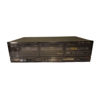
Do you have a question about the Pioneer CT-1040W and is the answer not in the manual?

Pioneer CT-1040W Specifications

General IconGeneral
BrandPioneer
ModelCT-1040W
CategoryTape Deck
LanguageEnglish

Summary

1. SPECIFICATIONS

General Specifications

Details system, heads, motor, wow/flutter, frequency response, S/N, distortion, and input/output levels.

Subfunctions and Miscellaneous Details

Lists additional features, power requirements, dimensions, weight, and furnished parts.

2. FRONT PANEL FACILITIES

Front Panel Controls and Indicators

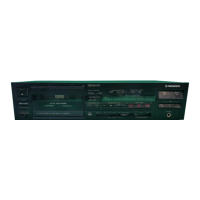
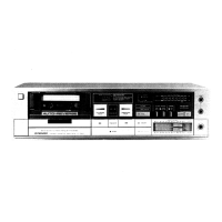
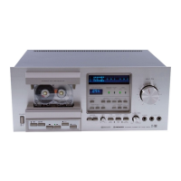
Details on power, play, stop, FF, REW, pause, REC/MUTE, eject, indicators, and meters.

Special Function Controls

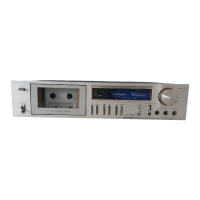
Covers Music Search, Pitch Control, Tape Counter, Reset, Copy, High Speed, Relay Play, Synchro Rec.

3. DISASSEMBLY

Front Panel Controls Description

Details on recording level, Dolby NR, Phones, MIC/Headphone jacks, and indicators.

Disassembly Procedures

Step-by-step instructions for disassembling the unit.

4. PARTS LOCATION

Front Panel Parts Identification

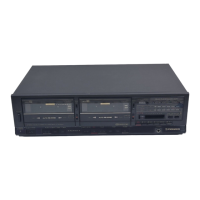
Identifies parts on the front panel and with the panel removed.

5. EXPLODED VIEW AND PARTS LIST

Main Assembly Parts List

Detailed list of parts for the main assembly with exploded view.

Mechanism Unit (Deck B) Parts List

Exploded view and parts list for Mechanism Unit B.

Mechanism Unit (Deck A) Parts List

Exploded view and parts list for Mechanism Unit A.

7. P.C.BOARDS CONNECTION DIAGRAM

Main Assembly Connection Diagram

Shows connections for the main PC board.

Transistor Assembly Diagrams

Connection diagrams for transistor assemblies.

9. ELECTRICAL PARTS LIST

Resistors and Capacitors

Lists resistors and capacitors with part numbers and symbols.

Semiconductors and Miscellaneous Parts

Lists semiconductors and other parts with numbers and symbols.

10. ADJUSTMENTS

10.1 MECHANICAL ADJUSTMENTS

Procedures for cleaning and adjusting mechanical parts.

10.2 ELECTRICAL ADJUSTMENTS

Electrical Adjustment Prerequisites

Conditions and tools needed before electrical adjustments.

Deck A Electrical Adjustments

Procedures for Head Azimuth, Playback Equalizer, and Level adjustments for Deck A.

Deck B Electrical Adjustments

Procedures for Dolby NR, Head Azimuth, Playback Equalizer, and Level adjustments for Deck B.

Recording Level Adjustment

Adjusting recording level for different tape types.

11. SAFETY INFORMATION

Safety Precautions and Leakage Current Check

Includes leakage current check procedures and warnings.

Product Safety Notice

Highlights safety-related characteristics of replacement parts.

12. SUPPLEMENT FOR HE, HB AND HP TYPES

Specifications and Part Differences

Details differences in specifications and miscellaneous parts for HE, HB, HP models.

13. SUPPLEMENT FOR D AND D/G TYPES

Specifications and Part Differences

Details differences in specifications and miscellaneous parts for D and D/G models.

Related product manuals