Do you have a question about the Pioneer CT-F505 and is the answer not in the manual?
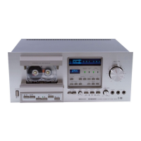
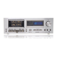
Explains the function of front panel buttons, switches, and indicators.
Describes the MIC and PHONES jacks on the front panel.
Details the function of FF, REW, STOP/EJECT, REC, PLAY, and PAUSE levers.
Covers power cord safety, internal part handling, and head care.
Step-by-step guide to remove the front panel, stay, and mechanism.
Instructions for removing the pinch roller.
Steps to remove the take-up reel base.
Procedure for removing the flywheel, belt, and motor.
Steps to remove the supply reel base.
Identifies parts on the front panel with labels.
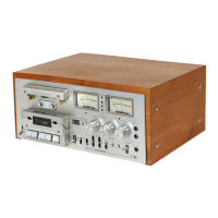
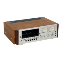
Identifies components on the top and rear panels.
Illustrates the main functional blocks and signal flow of the cassette deck.
Shows signal levels in dBV throughout the playback and recording circuits.
Describes the signal path for recording and playback circuits.
Explains various amplifier circuits including mic, flat, recording, and headphone.
Explains the Dolby IC and its operation modes.
Explains the muting circuit operation during pause and stop states.
Details the muting release mechanism during play and record.
Describes the oscillator circuit for erase and bias current.
Explains the power supply circuit and its different systems.
Explains the mechanical processes for play and auto-stop functions.
Describes the mechanical operation for fast forward and rewind modes.
General precautions before performing mechanical adjustments.
Steps to adjust the tape speed using a frequency counter.
Procedures for adjusting motor switch and FF/REW switch operation.
Steps to adjust the pinch roller pressure.
How to measure and adjust reel base torque.
Adjustments for play switch and leaf switch timing.
Procedure for adjusting the pause timing mechanism.
Checks and preparations before starting electrical adjustments.
Steps to adjust the head azimuth for optimal playback.
How to check the playback equalizer response.
Procedure to adjust playback level, including Dolby level.
Steps to calibrate the level meters to 0dB.
Initial adjustment of recording current.
Procedure for initial bias adjustment.
Adjusting frequency response for recording and playback.
Procedure to set the recording input level.
Steps to properly adjust the Dolby circuit.
Lists miscellaneous parts used in the equipment.
Shows how various components and modules are connected.
Provides the detailed electronic schematic diagram of the device.
Provides the schematic and parts list for the Dolby assembly.
Shows the schematic and parts list for the indicator assembly.
Provides the schematic and parts list for the terminal board assembly.
Explains the coding system used for resistor values in Pioneer equipment.
Exploded view of the bonnet and bottom cover parts.
Exploded view of the panel and associated parts.
Exploded view of the chassis and its components.
Exploded view of the door assembly and its parts.
Exploded view of the first part of the mechanism.
Exploded view of the second part of the mechanism.
Exploded view of pulleys and idlers.
Exploded views of the control buttons and head base assembly.
Exploded view of the reel base assemblies.
Details the procedure for packing the unit for shipment.