EasyManua.ls Logo

Pioneer CT-X50 User Manual

Pioneer CT-X50
47 pages
To Next Page IconTo Next Page
Page #1 background imageLoading...
Page #1 background image
c)rrIoNEER'
ORDER
NO.
ARP-OO6-O
STEREO CASSETTE
DECK
MODEL
CT-X5O COMES IN FIVE
VERSIONS
DISTINGUISHED
AS
FOLLOWS:
o
This
service
manual
is applicable
to
the KU type. For
servicing
of the
other types,
please
refer
to the
additional
service manual.
o
Ce
manuel
d'instruction
se
refère
au
mode
de réglage, en français.
o
Este
manual de
servicio
trata del método
de
ajuste
escrito en espafiol.
1.
2.
3.
4.
5.
6.
7.
2
3
4
5
7
15
"17
8.
9.
10.
11.
12.
P.C.BOARDS
CONNECTION
D IAGRAM
SHEMATIC
DIAGRAM
ELECTRICAL
PARTS
LIST
PACKING
ADJUSTMENT.
REGLAGE
ADJUSTE
Type
Voltago
Remarks
KU
12OV
only
U.S.A model
r{E
22OY
and 24OV
(Switchablel
Europe
model
HB
22OY
and 240V
(Switchabte)
U.K.
model
D
12OV,22OV
and
240V
(Switchabtel
General
export model
D/G
1
2OV, 22OV
and 24O
(Switchablel
U.S. military model
CONTENTS
SPECIFICATIONS
FRONT
PANEL FACI
LITIES
.
DISASSEMBLY
PARTS
LOCATION
CIRCUIT DESCRIPTIONS.
BLOCK DIAGRAM
EXPLODED
VlEWS
AND
PARTS
LIST
24
27
30
32
33
40
47
PfONEEFI
ELECTFICINIC
CC|FIPCIFIATIEIN
4-1.
.v'esuro
I
-chome.
Meeuno-ku.
Tokyo
j
s3. Jêpân
U.a. F|CTNICF| ILICTF|CINICa
CCIF|PCIFIAI|CIN
BS
Oxro.d
D.rve.
Moonêchre.
New Jensev
O7O74.
US A
FlGlNlll|
CLCCTFICINIC
(É9F|C!FE!
N.\/.
LurEhegen-Hêven
g,
2OSO Ancwenp.
E}etgrum
FfClNllF
lLlCIFlClJ\|lCa
AUaTFALIA
F1Y.
L1Ct.
17A-1e4
Eloundê.v
Ftoêd,
BnBèsrcte. VrcEoFrâ 31S8.
AusE.Êtrs
FZ
O
J
ULY
1981
Printed
in
Japan
Question and Answer IconNeed help?

Do you have a question about the Pioneer CT-X50 and is the answer not in the manual?

Pioneer CT-X50 Specifications

General IconGeneral
Track System4-track, 2-channel stereo
Tape Speed4.8 cm/s
Heads1 x record/playback, 1 x erase
MotorDC servo motor
Tape TypeType I, CrO2, Metal
Total Harmonic Distortion1.0%
Noise ReductionDolby B, Dolby C
TypeCassette Deck
OutputsHeadphones
InputsLine in

Summary

5. CIRCUIT DESCRIPTIONS

5.1 SIGNAL PATH

Explains signal flow for recording and playback modes.

5.2 CONTROL CIRCUIT & MECHANISMS

Describes control circuit, power-assist, and tape transport modes.

5.3 MUTING CIRCUIT & AUTO-STOP

Details muting gate, auto-stop, and muting operation modes.

5.5 FUNCTION SELECTOR & TIMING

Covers function selector, auto tape selector, and timing charts.

4. PARTS LOCATION

Panel Views and Top Views

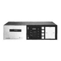
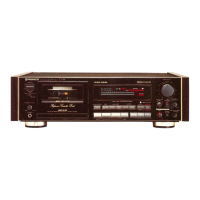
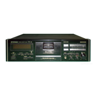
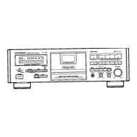
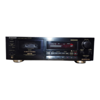
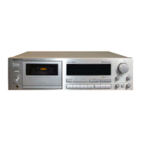
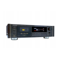
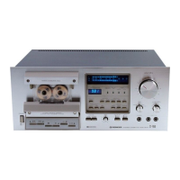
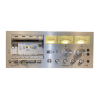
Identifies components on front, rear, top, and removed panels.

7. EXPLODED VIEWS AND PARTS LIST

7.1 EXTERIOR PARTS

Provides an exploded view of the exterior parts.

Part List

Lists all parts with their numbers, descriptions, and marks.

6. BLOCK DIAGRAM

7.2 MECHANISM ASSEMBLY

Mechanism Parts List

Lists all parts specifically for the mechanism assembly.

7. External Appearance of Transistors and ICs

11. PACKING

8. P.C.BOARDS CONNECTION DIAGRAM

9. SCHEMATIC DIAGRAM

10. ELECTRICAL PARTS LIST

Capacitors, Resistors, and Semiconductors

Lists electrical components like capacitors, resistors, and semiconductors.

12. RÉGLAGES

Mechanical Adjustments (Pinch Roller, Torque, Speed, Detection)

Covers pinch roller, torque, speed, and cassette detection adjustments.

Mechanism Solenoid Adjustments

Adjusts FF/REW solenoids and detection assembly.

Electrical Adjustments (Frequency, Levels, Dolby NR)

Adjusts frequency response, levels, Dolby NR, and head azimuth.

Electrical Checks (Limiter, Auto Play)

Performs limiter effect check and auto play movement verification.

Related product manuals