Do you have a question about the Pioneer CT-F700 and is the answer not in the manual?
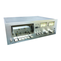
Steps for removing exterior components like the bonnet and front panel.
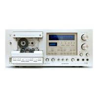
Method for removing and replacing front panel buttons.
Procedures for replacing tape indicator lamp, reel turntables, and belts.
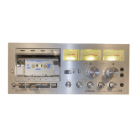
Explanation of the dynamic level and bias meters' functions.
Indicates input level during recording and output level during playback.
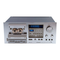
Describes MIC and PHONES jacks.
Controls for input/output signal levels.
Diagram illustrating signal levels during playback stages.
Diagram illustrating signal levels during recording stages.
Labeled diagram showing parts on the front panel assembly.
Labeled diagram of components visible after front panel removal.
Description of circuits used for recording and playback functions.
Detailed explanation of the Dolby B noise reduction system.
Describes oscillator and muting circuits.
Describes control and meter circuits.
Procedure for adjusting pinch roller pressure.
Procedures for reel torque, tape speed, pause, and motor timing.
Details on packing materials used for the CT-F700D/G.
List of miscellaneous parts used in the equipment.
Schematics/parts for Muting, Control, Meter, Power assemblies.
Exploded view of the exterior parts.
Explanation of resistor value codes.
Exploded view of the mother assembly.
Lists of assemblies, transformers, switches, capacitors, and fuses.
Description of the CT-F700/KU circuitry, noting differences.
List of miscellaneous parts specific to CT-F700/KU.
Schematic diagram for CT-F700/KU.
Schematic diagram of the mother assembly for CT-F700/KU.
List of miscellaneous parts specific to CT-F700/KC.
Details on the power supply assembly for CT-F700/KC.
Information on mother assembly changes for CT-F700/KC.
List of miscellaneous parts specific to CT-F700/HG.
Schematic diagram of the amplifier assembly for CT-F700/HG.
Schematic diagram for CT-F700/HG.
Schematic diagram of the fuse assembly for CT-F700/HG.
| Track System | 4-Track, 2-Channel Stereo |
|---|---|
| Motor | DC servo motor |
| Type | Cassette Deck |
| Tape Type | Type I, CrO2 |
| Inputs | Line |
| Outputs | Line |
| Frequency Response | 20Hz - 20kHz |