Do you have a question about the Pioneer CT-110 and is the answer not in the manual?
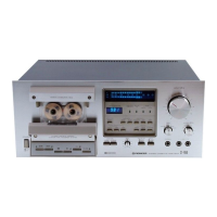
Controls power on/off and activates muting circuit.
Opens and closes the cassette holder for tape access.
Buttons for tape operation: REC, REW, PLAY, FF, STOP, Pause.
Selects bias and equalization for NORM, CrO2, METAL tapes.
Activates the Dolby noise reduction system.
Input jacks for connecting microphones for recording.
Adjusts input signal level for recording.
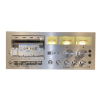
Displays input/output signal levels during recording/playback.
Amplifies and equalizes audio signals during playback.
Processes input signals and amplifies them for recording.
Manages deck operations using IC PM9002B and auto-stop function.
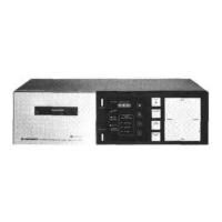
Procedure for removing the top cover of the unit.
Steps to detach the cassette door from the unit.
Steps to remove the volume control and panel assembly.
Procedure for removing the tape counter unit.
Steps to detach the display assembly from the front panel.
Procedure for removing the entire front panel assembly.
Instructions for removing the main mechanical drive system.
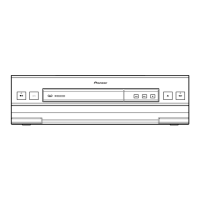
Diagram showing parts and their locations on the front panel.
Adjusts pinch roller pressure for proper tape contact.
Measures and adjusts torque for supply and take-up reel bases.
Adjusts tape playback speed using a variable resistor.
Adjusts the position of the FF solenoid for correct operation.
Adjusts the position of the REW solenoid for correct operation.
Sets the Dolby NR level for accurate noise reduction during playback.
Aligns the playback head for optimal high-frequency response.
Sets the playback signal output level for each channel.
Verifies playback frequency response across different tape types.
Checks the accuracy and response of the level meter segments.
Adjusts recording and playback frequency response for optimal sound.
| Track System | 4-track, 2-channel stereo |
|---|---|
| Tape Speed | 4.8 cm/s |
| Total Harmonic Distortion | 1.0% |
| Output | 0.5V (line) |
| Type | Cassette Deck |
| Motor | DC servo motor |
| Frequency Response | 30Hz to 16kHz |
| Signal-to-Noise Ratio | 58dB |
| Input | Line in |
| Dimensions | 420 x 120 x 300 mm |