EasyManua.ls Logo

Pioneer DEH-1780 - User Manual

Pioneer DEH-1780
62 pages
Print Icon
To Next Page IconTo Next Page
Loading...
ORDER NO.
PIONEER CORPORATION 4-1, Meguro 1-chome, Meguro-ku, Tokyo 153-8654, Japan
PIONEER ELECTRONICS (USA) INC. P.O. Box 1760, Long Beach, CA 90801-1760, U.S.A.
PIONEER EUROPE NV Haven 1087, Keetberglaan 1, 9120 Melsele, Belgium
PIONEER ELECTRONICS ASIACENTRE PTE. LTD. 253 Alexandra Road, #04-01, Singapore 159936
PIONEER CORPORATION 2004
DEH-1750/XN/GS
CRT3377
HIGH POWER CD PLAYER WITH FM/AM TUNER
DEH-1750
/XN/GS
DEH-1770
/XN/CS
This service manual should be used together with the following manual(s):
Model No. Order No. Mech.Module Remarks
CX-3110 CRT3178 S10.1 CD Mech. Module:Circuit Description, Mech. Description, Disassembly
For details, refer to "Important Check Points for Good Servicing".
K-ZZW. OCT. 2004 printed in Japan
Question and Answer IconNeed help?

Do you have a question about the Pioneer DEH-1780 and is the answer not in the manual?

Overview

This document is a service manual for the Pioneer DEH-1750/XN/GS and DEH-1770/XN/CS high-power CD players with FM/AM tuners. It provides detailed information for servicing, including specifications, exploded views, parts lists, block diagrams, schematic diagrams, PCB connection diagrams, electrical parts lists, adjustment procedures, error modes, general information, and operational instructions.

Function Description

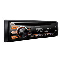
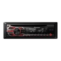
The Pioneer DEH-1750/XN/GS and DEH-1770/XN/CS are in-car audio systems designed to provide high-quality sound reproduction from CDs and radio broadcasts. They feature a high-power amplifier for robust audio output and an integrated FM/AM tuner for radio reception. The units are designed for ease of use and maintenance, with specific procedures outlined for various servicing tasks.

Important Technical Specifications

General

  • Rated Power Source: 14.4 V DC (allowable voltage range: 12.0–14.4 V DC)
  • Grounding System: Negative type
  • Max. Current Consumption: 10.0 A
  • Backup Current: 5 mA or less
  • Dimensions (W x H x D):
    • DIN Chassis: 178 × 50 × 157 mm
    • DIN Nose: 188 × 58 × 18 mm
    • D Chassis: 178 × 50 × 162 mm
    • D Nose: 170 × 48 × 13 mm
  • Weight: 1.3 kg
  • Number of Channels: 2 (stereo)

Audio

  • Continuous Power Output: 20 W per channel minimum into 4 ohms, both channels driven 50 to 15,000 Hz with no more than 5% THD.
  • Maximum Power Output: 45 W x 4
  • Load Impedance: 4 Ω (4–8 Ω allowable)
  • Preout Max Output Level/Output Impedance: 2.2 V/1 kΩ
  • Bass/Treble:
    • Bass Frequency: 100 Hz
    • Bass Gain: ±12 dB
    • Treble Frequency: 10 kHz
    • Treble Gain: ±12 dB
  • Loudness Contour:
    • Low: +7 dB (100 Hz), +4 dB (10 kHz)
    • High: +10 dB (100 Hz), +6.5 dB (10 kHz) (volume: -30 dB)

FM Tuner

  • Frequency Range: 87.5–108.0 MHz
  • Usable Sensitivity: 8 dBf (0.7 µV/75 Ω, mono, S/N: 30 dB)
  • 50 dB Quieting Sensitivity: 10 dBf (0.9 µV/75 Ω, mono)
  • Signal-to-Noise Ratio: 75 dB (IEC-A network)
  • Distortion:
    • 0.3% (at 65 dBf, 1 kHz, stereo)
    • 0.1% (at 65 dBf, 1 kHz, mono)
  • Frequency Response: 30–15,000 Hz (±3 dB)
  • Stereo Separation: 45 dB (at 65 dBf, 1 kHz)

AM Tuner

  • Frequency Range:
    • 531–1,602 kHz (9 kHz) for DEH-1750/XN/GS
    • 530–1,640 kHz (10 kHz) for DEH-1770/XN/CS
  • Usable Sensitivity: 18 µV (S/N: 20 dB)
  • Signal-to-Noise Ratio: 65 dB (IEC-A network)

CD Player

  • System: Compact disc audio system
  • Usable Discs: Compact disc
  • Signal Format:
    • Sampling Frequency: 44.1 kHz
    • Number of Quantization Bits: 16; linear
  • Frequency Characteristics: 5–20,000 Hz (±1 dB)
  • Signal-to-Noise Ratio: 94 dB (1 kHz) (IEC-A network)
  • Dynamic Range: 92 dB (1 kHz)

Usage Features

The head unit offers a range of controls for audio playback and settings:

  • CLOCK button: Changes the clock display.
  • BTB button: Selects various BTB (bass treble booster) settings.
  • Disc loading slot: Inserts a disc for playback.
  • LOUDNESS button: Turns loudness on or off.
  • EJECT button: Ejects a CD from the built-in CD player.
  • AUDIO button: Selects various sound quality controls.
  • ◀/▶ buttons: Used for manual seek tuning, fast forward, reverse, and track search. Also used for controlling functions.
  • DETACH button: Removes the front panel from the head unit.
  • BAND button: Selects among three FM bands and one AM band, and cancels the control mode of functions.
  • LOCAL/BSM button: Turns local function on or off. Press and hold to turn BSM function on or off.
  • 1-6 buttons: Used for preset tuning.
  • SOURCE button: Turns the unit on by selecting a source. Cycles through all available sources.
  • VOLUME (+/-) buttons: Increases or decreases the volume.

CD Playback Features

  • Track number indicator: Shows the current track playing.
  • Play time indicator: Shows the elapsed playing time of the current track.
  • Loading a CD: Insert a CD into the loading slot; playback starts automatically. Ensure the label side of the disc is up.
  • Adjusting sound level: Use the VOLUME buttons.
  • Fast forward/reverse: Press and hold ◀ or ▶.
  • Skip tracks: Press ◀ or ▶ to skip back or forward.
  • Random play: Press button 4 repeatedly to turn random play on or off. "RDM" appears on the display when active.
  • Repeating play: Press button 5 repeatedly to turn repeat play on or off. "RPT" appears on the display when active.
  • Pausing CD playback: Press button 6 repeatedly to turn pause on or off. "PAUSE" appears on the display when active.

Maintenance Features

The service manual provides comprehensive guidelines for servicing the device, emphasizing product safety and quality.

Important Check Points for Good Servicing

  • Product Safety:
    • Use specified genuine parts for repair.
    • Do not perform modifications without proper instructions.
    • Ensure proper soldering of repaired locations.
    • Make sure all screws are tightly fastened and connectors are correctly inserted.
    • Replace wiring cables to their original state, ensuring no pinched wires.
    • Check that no screws or soldering scraps remain inside the product.
    • Inspect the power cord for any damage (semi-broken wires, scratches, melting) and replace if necessary.
    • Check the power plug for spark traces and advise on secure connections.
    • Maintain a safe servicing environment, paying attention to static electricity and surrounding articles.
  • Adjustments: Perform adjustments according to the manual to maintain original product performance and characteristics within specifications.
  • Lubricants, Glues, and Replacement Parts: Use specified substances in proper amounts.
  • Cleaning: Perform proper cleaning for parts requiring it (e.g., optical pickups) to restore performance.
  • Shipping Mode and Shipping Screws: Set shipping mode or install shipping screws to protect products during transit, especially if specified in the manual.

CD Adjustment

  • Cautions:
    • The reference voltage REFO1 (1.65V) is used instead of GND for the regulator. Avoid shorting REFO1 with GND during adjustment to prevent misoperation and damage to the pickup.
    • Ensure measuring instruments are set to floating state to avoid potential differences with REFO1.
    • Turn off the regulator or power immediately if REFO1 is mistakenly connected to GND.
    • Turn off the regulator before mounting/removing filters or leads for adjustment.
    • Allow the mechanism to operate for at least one minute after the regulator is turned on for stable circuit operation.
    • Avoid mechanical or electrical shock to the mechanism during adjustment in test mode.
    • Insert a 1k ohm resistor in series when observing RFI and RFO signals to prevent oscillation.
    • Load and eject operations are not guaranteed with the mechanism upside down. Reset the product or cycle ACC power if the mechanism is blocked.
  • Test Mode:
    • Enter by pressing buttons 4 and 6 simultaneously while resetting.
    • Exit by turning off ACC and backing up.
    • Notes: Avoid pressing keys other than EJECT during ejection. Turn off power immediately if focus search keys are pressed to protect the actuator. Track jump operations continue even if the key is released. Tracking loop closes during CRG move and 100TR jump modes. Jump mode, RF amp gain, and auto-adjustment values reset to default settings when power is cycled.

Checking the Grating After Changing the Pickup Unit

  • Purpose: To ensure the grating angle of the PU unit is within an acceptable range after replacement.
  • Symptoms of Mal-adjustment: Inability to close tracking, difficulty performing track search, or prolonged track searching.
  • Method: Use an oscilloscope and L.P.F. to monitor E, F, and REFO1 points with a TCD-782 disc in TEST MODE.
  • Procedure:
    1. Load disc and switch on 3V regulator in test mode.
    2. Move PU unit to innermost track using ◀ and ▶ buttons.
    3. Press key 3 to close focus (display "91"). Press key 2 for tracking balance adjustment (display "81"). Press key 3 again (display returns to "81").
    4. Monitor LPF outputs on oscilloscope and check that phase difference is within 75°.
    5. If the phase difference exceeds 75°, try changing the PU unit. If it remains above 75° after multiple attempts, the mechanism is faulty.
  • Note: Grating waveform may "wobble" due to disc eccentricity or clamping center misalignment; the specified angle refers to the average angle. Reloading the disc may reduce "wobble."

Error Mode

  • Function: If the CD player stops due to an error, an error code is displayed to help diagnose the problem.
  • Display: Error codes are shown in DMIN (minutes display area) and DSEC (seconds display area) when SERRORM is selected in CSMOD. Display format varies (8-digit, 6-digit, or 4-digit).
  • Error Code List (Examples):
    • 10 (Electricity): Carriage Home NG / SERVO LSI Communication Error (CRG cannot move to inner diameter, failure on home switch or CRG move mechanism, communication error between microcomputer and SERVO LSI).
    • 11 (Electricity): Focus Servo NG (Focusing not available, stains on rear side of disc, or excessive vibrations on REWRITABLE).
    • 12 (Electricity): Spindle Lock NG / Subcode NG (Spindle not locked, sub-code is strange, damaged disc, CD-R data not found, turned-over disc, CD signal error).
    • 17 (Electricity): Setup NG (AGC protection not working, focus easily lost, damaged disc, excessive vibrations).
    • 30 (Electricity): Search Time Out (Failed to reach target address, CRG tracking error or damages on disc).
    • 44 (Electricity): ALL Skip (Skip setting for all track, CD-R/RW).
    • 50 (Mechanism): CD On Mech Error (Mechanical error during CD ON, defective loading motor, mechanical lock and mechanical sensor).
    • A0 (System): Power Supply NG (Power (VD) is ground faulted, failure on SW transistor or power supply).
  • Remarks: Mechanical errors are not displayed. Unreadable TOC is not an error. Upper digits of error codes are subdivided (1x: Setup, 3x: Search, Ax: Other).

System Microcomputer Test Program

  • PCL Output: In normal operation mode (detachable panel installed, ACC ON, standby mode cancelled), shifting TESTIN (Pin 15) to H outputs a clock signal from PCL (Pin 14). The frequency should be 786.432kHz ± 31.5Hz. If out of range, replace X'tal (X601).

Cleaning

  • Procedure: Before shipping, clean specified portions using prescribed tools.
  • CD Pickup Lenses: Clean with cleaning liquid (GEM1004) and cleaning paper (GED-008).

Pioneer DEH-1780 Specifications

General IconGeneral
BrandPioneer
ModelDEH-1780
CategoryCar Receiver
LanguageEnglish

Related product manuals