EasyManua.ls Logo

Pioneer DEH-2030R User Manual

Pioneer DEH-2030R
85 pages
To Next Page IconTo Next Page
Page #1 background imageLoading...
Page #1 background image
PIONEER ELECTRONIC CORPORATION 4-1, Meguro 1-Chome, Meguro-ku, Tokyo 153-8654, Japan
PIONEER ELECTRONICS SERVICE INC. P.O.Box 1760, Long Beach, CA 90801-1760 U.S.A.
PIONEER ELECTRONIC [EUROPE] N.V. Haven 1087 Keetberglaan 1, 9120 Melsele, Belgium
PIONEER ELECTRONICS ASIACENTRE PTE.LTD. 253 Alexandra Road, #04-01, Singapore 159936
C PIONEER ELECTRONIC CORPORATION 1998
K-ZZD. DEC. 1998 Printed in Japan
ORDER NO.
CRT2312
HIGH POWER CD PLAYER WITH RDS TUNER
DEH-2000R X1N/EW
Service
Manual
CONTENTS
1. SAFETY INFORMATION ............................................2
2. EXPLODED VIEWS AND PARTS LIST.......................3
3. SCHEMATIC DIAGRAM ...........................................14
4. PCB CONNECTION DIAGRAM ................................38
5. ELECTRICAL PARTS LIST ........................................48
6. ADJUSTMENT..........................................................56
7. GENERAL INFORMATION .......................................60
7.1 PARTS .................................................................60
7.1.1 IC................................................................60
7.1.2 DISPLAY....................................................67
7.2 DIAGNOSIS ........................................................68
7.2.1 DISASSEMBLY .........................................68
7.2.2 TEST MODE..............................................69
7.3 BLOCK DIAGRAM ..............................................73
8. OPERATIONS AND SPECIFICATIONS.....................75
- See the separate manual CX-916(CRT2300) for the CD mechanism description, disassembly and circuit
description.
- The CD mechanism employed in this model is one of S8 series.
DEH-2030R X1N/EW
DEH-2020R X1N/GR
DEH-2000R/X1N/EW
Question and Answer IconNeed help?

Do you have a question about the Pioneer DEH-2030R and is the answer not in the manual?

Pioneer DEH-2030R Specifications

General IconGeneral
BrandPioneer
ModelDEH-2030R
CategoryCar Receiver
LanguageEnglish

Summary

Safety Information

CD Player Service Precautions

General safety precautions for CD player servicing and handling.

Safety Precautions for Servicing

Safety measures for technicians, including laser diode handling and distances.

Exploded Views and Parts List

Packing Section

Exploded view and parts list for product packing.

Owner's Manuals and Installation Manuals

List of included manuals and their part numbers.

Exterior Section

Exploded view diagrams and parts lists for exterior components.

CD Mechanism Module Section

Exploded view diagrams and parts lists for the CD mechanism module.

Schematic Diagrams

Overall Connection Diagram (DEH-2000R/X1N/EW, DEH-2030R/X1N/EW)

Overall schematic showing unit connections for specific models.

Overall Connection Diagram (DEH-2020R/X1N/GR)

Overall schematic showing unit connections for a specific model.

FM/AM Tuner Unit Schematic (DEH-2000R/X1N/EW, DEH-2030R/X1N/EW)

Schematic diagram for the FM/AM Tuner Unit for specific models.

FM/AM Tuner Unit Schematic (DEH-2020R/X1N/GR)

Schematic diagram for the FM/AM Tuner Unit for a specific model.

Keyboard Unit Schematic

Schematic diagram for the Keyboard Unit.

CD Mechanism Module Block Diagram

Block diagram illustrating connections for the CD mechanism module.

Block Diagram

General Block Diagram

General block diagram of the system's major functional units.

PCB Connection Diagrams

Tuner Amp Unit PCB (Side A)

PCB layout for the Tuner Amp Unit (Side A).

Tuner Amp Unit PCB (Side B)

PCB layout for the Tuner Amp Unit (Side B).

FM/AM Tuner Unit PCB (Side A)

PCB layout for the FM/AM Tuner Unit (Side A).

FM/AM Tuner Unit PCB (Side B)

PCB layout for the FM/AM Tuner Unit (Side B).

Keyboard Unit PCB (Side A)

PCB layout for the Keyboard Unit (Side A).

Keyboard Unit PCB (Side B)

PCB layout for the Keyboard Unit (Side B).

CD Mechanism Module PCB (Side A)

PCB layout for the CD Mechanism Module (Side A).

CD Mechanism Module PCB (Side B)

PCB layout for the CD Mechanism Module (Side B).

Electrical Parts List

Miscellaneous Components

List of miscellaneous electronic components and their part numbers.

Resistors

List of resistors with circuit symbols, part names, and part numbers.

Capacitors

List of capacitors with circuit symbols, part names, and part numbers.

ICs, Transistors, Diodes, etc.

List of integrated circuits, transistors, and diodes with part numbers.

Adjustment

CD Adjustment Precautions

Precautions for CD mechanism adjustments, including power and grounding.

CD Adjustment Test Mode

Procedure and notes for entering and using the CD mechanism test mode.

CD Adjustment Flow Chart

Flow chart for CD mechanism adjustments and test modes.

Checking Grating After Pickup Unit Change

Procedure to check grating angle after PU unit replacement.

General Information

IC Pin Functions

Pin functions and operations for various ICs used in the unit.

Display Pinout

Pinout description for the CAW1499 display.

Disassembly Procedures

Step-by-step instructions for disassembling external and internal components.

Test Mode Procedures and Error Codes

Test modes, error codes, and their causes for troubleshooting.

Operations and Specifications

Head Unit Key Finder

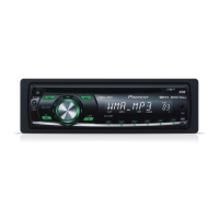
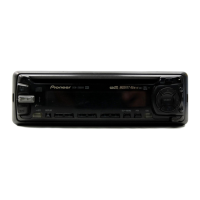
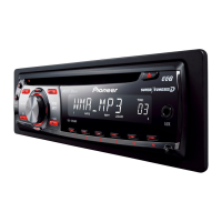
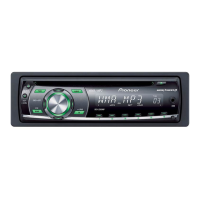
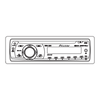
Diagram identifying the location of buttons and controls on the head unit.

Basic Operation - To Listen to Music

Guide to initial operations for listening to music, including source selection and volume.

Basic Operation of Tuner

How to perform manual and seek tuning, and preset station recall.

Basic Operation of Built-in CD Player

Instructions for CD player operation, including eject and track search.

Audio Adjustment - Equalizer Settings

How to select and adjust equalizer curves and audio menu settings.

Audio Adjustment - Balance and EQ Fine Tuning

Detailed Fader/Balance and EQ curve adjustments via Audio Menu.

Audio Adjustment - Loudness and FIE

Adjustments for Loudness, EQ fine tuning, and Front Image Enhancer.

Audio Adjustment - Source Level Adjustment (SLA)

Function to prevent volume leaps when switching between sources.

External Wiring Diagram

Diagram showing external connections and wiring for the unit.

Technical Specifications

Specifications for general, amplifier, FM, MW, and LW tuner sections.

Related product manuals