EasyManua.ls Logo

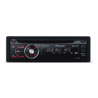
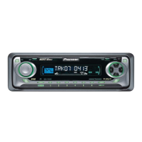
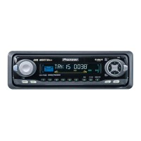
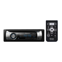
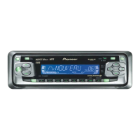
Pioneer DEH-P400 User Manual

Pioneer DEH-P400
85 pages
To Next Page IconTo Next Page
Page #1 background imageLoading...
Page #1 background image
PIONEER ELECTRONIC CORPORATION 4-1, Meguro 1-Chome, Meguro-ku, Tokyo 153-8654, Japan
PIONEER ELECTRONICS SERVICE INC. P.O.Box 1760, Long Beach, CA 90801-1760 U.S.A.
PIONEER ELECTRONIC [EUROPE] N.V. Haven 1087 Keetberglaan 1, 9120 Melsele, Belgium
PIONEER ELECTRONICS ASIACENTRE PTE.LTD. 253 Alexandra Road, #04-01, Singapore 159936
C PIONEER ELECTRONIC CORPORATION 1998
K-ZZD. DEC. 1998 Printed in Japan
ORDER NO.
CRT2308
MULTI-CD CONTROL HIGH POWER CD PLAYER WITH FM/AM TUNER
DEH-P400 X1N/UC
Service
Manual
CONTENTS
1. SAFETY INFORMATION ............................................2
2. EXPLODED VIEWS AND PARTS LIST.......................2
3. SCHEMATIC DIAGRAM ...........................................12
4. PCB CONNECTION DIAGRAM ................................34
5. ELECTRICAL PARTS LIST ........................................44
6. ADJUSTMENT..........................................................53
7. GENERAL INFORMATION .......................................57
7.1 PARTS .................................................................57
7.1.1 IC................................................................57
7.1.2 DISPLAY....................................................64
7.2 DIAGNOSIS ........................................................65
7.2.1 DISASSEMBLY .........................................65
7.2.2 TEST MODE..............................................66
7.3 BLOCK DIAGRAM ..............................................70
8. OPERATIONS AND SPECIFICATIONS.....................72
- See the separate manual CX-916(CRT2300) for the CD mechanism description, disassembly and circuit
description.
- The CD mechanism employed in this model is one of S8 series.
DEH-P4000 X1N/UC
DEH-P4050 X1N/ES
DEH-P400/X1N/UC
w
w
w
.
x
i
a
o
y
u
1
6
3
.
c
o
m
Q
Q
3
7
6
3
1
5
1
5
0
9
9
2
8
9
4
2
9
8
T
E
L
1
3
9
4
2
2
9
6
5
1
3
9
9
2
8
9
4
2
9
8
0
5
1
5
1
3
6
7
3
Q
Q
TEL 13942296513 QQ 376315150 892498299
http://www.xiaoyu163.com
Question and Answer IconNeed help?

Do you have a question about the Pioneer DEH-P400 and is the answer not in the manual?

Pioneer DEH-P400 Specifications

General IconGeneral
Power Output50 W x 4
RMS Power Output22 W x 4
TunerAM/FM
CD PlaybackYes
MP3 PlaybackYes
WMA PlaybackYes
AAC PlaybackNo
USB PortYes
BluetoothNo
DIN Size1 DIN
Detachable FaceYes
Preamp Voltage2 V
Number of Channels4
Display TypeLCD
AUX InputYes
Subwoofer OutputYes
AM/FM Presets24
Preamp Outputs2 pairs

Summary

1. SAFETY INFORMATION

CAUTION

Important warnings for qualified service technicians regarding product repair.

WARNING

Hazard warning about lead and chemicals in the product, as per California law.

2. EXPLODED VIEWS AND PARTS LIST

2.1 PACKING

Exploded view of packing components.

PACKING SECTION PARTS LIST

Detailed list of parts included in the product's packing.

CONTRAST TABLE

Compares parts used across different models (DEH-P400/P4000/P4050).

Owner's Manual

Lists part numbers for the Owner's Manual for different models.

Installation Manual

Lists part numbers for the Installation Manual for different models.

EXTERIOR SECTION PARTS LIST

Detailed list of external components and their part numbers.

CD MECHANISM MODULE SECTION PARTS LIST

Lists all parts related to the CD mechanism module.

3. SCHEMATIC DIAGRAM

3.1 OVERALL CONNECTION DIAGRAM(GUIDE PAGE)(DEH-P400/X1N/UC)

Overall connection diagram for the Tuner Amp Unit and System Controller.

3.2 OVERALL CONNECTION DIAGRAM(GUIDE PAGE)(DEH-P4000/X1N/UC, DEH-P4050/X1N/ES)

Overall connection diagram for Tuner Amp Unit for specific models.

3.3 FM/AM TUNER UNIT

Schematic diagram of the FM/AM Tuner unit.

3.4 KEYBOARD UNIT

Schematic diagram of the Keyboard Unit.

3.5 CD MECHANISM MODULE

Schematic diagram of the CD Mechanism Module and Control Unit.

4. PCB CONNECTION DIAGRAM

4.1 TUNER AMP UNIT

PCB layout diagram for the Tuner Amp Unit (Side A).

SIDE A (Main Unit)

PCB layout diagram for the main unit components (Side A).

4.2 FM/AM TUNER UNIT

PCB layout diagram for the FM/AM Tuner Unit (Side A).

SIDE B (FM/AM Tuner Unit)

PCB layout diagram for the FM/AM Tuner Unit (Side B).

4.3 KEYBOARD UNIT

PCB layout diagram for the Keyboard Unit (Side A).

SIDE B (Keyboard Unit)

PCB layout diagram for the Keyboard Unit (Side B).

4.4 CD MECHANISM MODULE

PCB layout diagrams for the CD Mechanism Module.

SIDE B (CD Mechanism Module)

PCB layout diagram for the CD Mechanism Module (Side B).

5. ELECTRICAL PARTS LIST

MISCELLANEOUS PARTS

Lists miscellaneous components like ICs, transistors, FETs, diodes, inductors, and buzzers.

RESISTORS LIST

Detailed list of resistors with circuit symbols, part names, and part numbers.

CAPACITORS LIST

Detailed list of capacitors with circuit symbols, part names, and part numbers.

6. ADJUSTMENT

6.1 CD ADJUSTMENT

Procedures for adjusting the CD mechanism, including precautions and test modes.

6.2 CHECKING THE GRATING AFTER CHANGING THE PICKUP UNIT

Procedure to check grating angle after replacing the pickup unit.

7. GENERAL INFORMATION

7.1 IC Pin Functions (PD4989A)

Detailed pin functions for the PD4989A IC.

7.1 IC Pin Functions (PD6294A)

Detailed pin functions for the PD6294A IC.

7.1 IC Pin Functions (UPD63710GC)

Detailed pin functions for the UPD63710GC IC.

7.1.2 DISPLAY

Display pin configurations for the CAW1498 LCD.

7.2 DIAGNOSIS

Procedures for disassembly and troubleshooting using test modes and error codes.

7.3 BLOCK DIAGRAM

Block diagrams illustrating the overall system architecture.

8. OPERATIONS AND SPECIFICATIONS

8.1 OPERATIONS

Guides on basic operations, including listening to music and using the head unit/remote.

Basic Operation of Tuner

Instructions for manual and seek tuning, and preset tuning of the radio.

Basic Operation of Built-in CD Player

How to switch displays, load discs, and perform track search/fast forward.

Basic Operation of Multi-CD Player

Instructions for multi-CD player operations like disc search and switching.

Audio Adjustment

Explains how to adjust equalizer curves, loudness, and sub-woofer settings.

8.2 SPECIFICATIONS

Technical specifications for the DEH-P400/X1N/UC and other models.

Related product manuals